Forming method of aeroengine hollow guide vane

An aero-engine and hollow diversion technology, which is applied in the direction of engine components, mechanical equipment, non-electric welding equipment, etc., can solve the problems of low welding pass rate, high labor intensity, high production cost, etc., to improve the strength of weld seam and improve production Efficiency, the effect of reducing production costs

Active Publication Date: 2014-02-19
AECC AVIATION POWER CO LTD
View PDF5 Cites 6 Cited by
  • Summary
  • Abstract
  • Description
  • Claims
  • Application Information

AI Technical Summary

Problems solved by technology

The flame brazing process is manually operated, which has high labor intensity and high production cost
When welding aluminum alloy materials, liquid aluminum absorbs hydrogen, resulting in a large number of welding defects such as pores and lack of fusion in the weld, resulting in a large number of scraps, and the welding pass rate is only 30% to 40%.

Method used


Image

  • Forming method of aeroengine hollow guide vane
  • Forming method of aeroengine hollow guide vane
  • Forming method of aeroengine hollow guide vane

Examples


Embodiment 1

[0030] The inner cavity thickness of the forged aero-engine hollow guide vane in this embodiment is 1.3mm, and the specific forming method adopts the following steps:

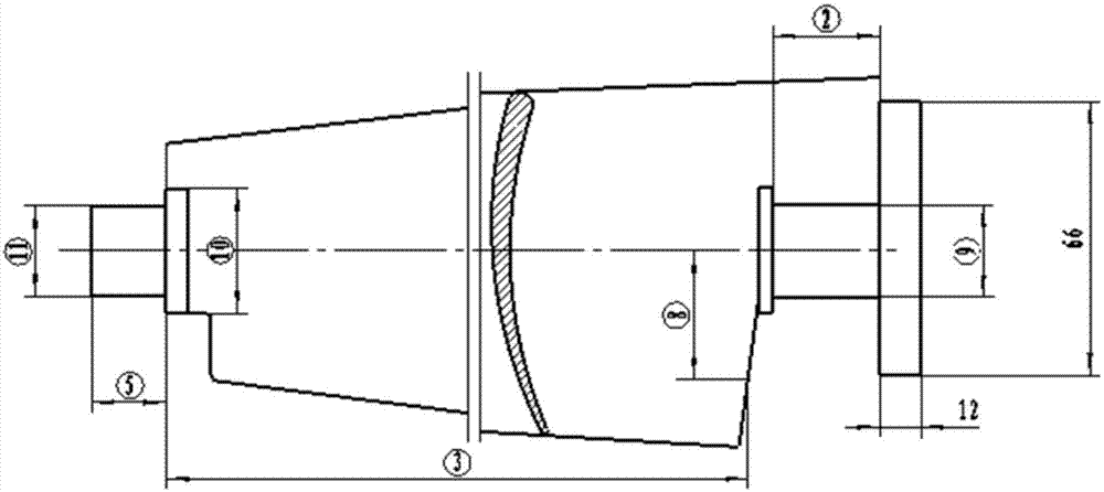
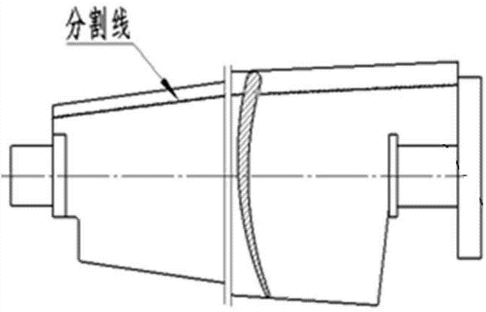
[0031] Step 1: Forge the blank of the main body of the blade and the blank of the exhaust edge insert respectively; the theoretical separation surface of the blade main body and the exhaust edge insert is obtained by extending the end face of the blade inner cavity close to the exhaust edge and extending 5mm toward the exhaust edge plane, and the blade main body blank and the exhaust edge insert blank each have a machining allowance extending 2.5 mm from the theoretical separation surface; the schematic diagram of the blade main body and the exhaust edge insert is shown in Figure 5 and Figure 6 shown.

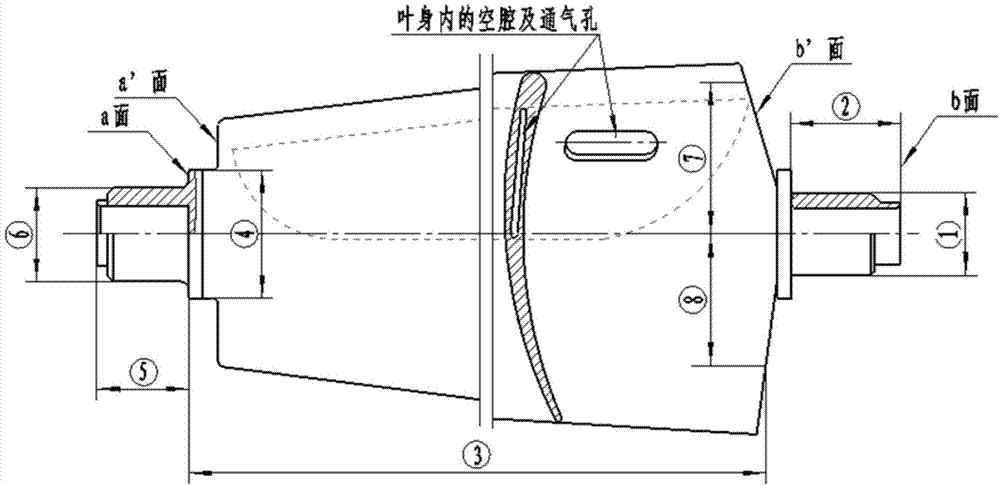
[0032] Such as figure 2 As shown, when forging the blank of the main body of the blade, a technical blade crown is forged on the b-side of one end of the main blade blank. The size of the technical blade cr...

Embodiment 2

[0040] The inner cavity thickness of the forged aero-engine hollow guide vane in this embodiment is 1.4mm, and the specific forming method adopts the following steps:

[0041] Step 1: Forge the blank of the main body of the blade and the blank of the exhaust edge insert respectively; the theoretical separation surface of the blade main body and the exhaust edge insert is obtained by extending the end face of the blade inner cavity close to the exhaust edge and extending 5mm toward the exhaust edge plane, and the blade main body blank and the exhaust edge insert blank each have a machining allowance extending 2.5 mm from the theoretical separation surface; the schematic diagram of the blade main body and the exhaust edge insert is shown in Figure 5 and Figure 6 shown.

[0042] Such as figure 2 As shown, when forging the blank of the main body of the blade, a technical blade crown is forged on the b-side of one end of the main blade blank. The size of the technical blade cr...

Embodiment 3

[0050] The inner cavity thickness of the forged hollow guide vane of the aero-engine in this embodiment is 1.5mm, and the specific forming method adopts the following steps:

[0051] Step 1: Forge the blank of the main body of the blade and the blank of the exhaust edge insert respectively; the theoretical separation surface of the blade main body and the exhaust edge insert is obtained by extending the end face of the blade inner cavity close to the exhaust edge and extending 5mm toward the exhaust edge plane, and the blade main body blank and the exhaust edge insert blank each have a machining allowance extending 2.5 mm from the theoretical separation surface; the schematic diagram of the blade main body and the exhaust edge insert is shown in Figure 5 and Figure 6 shown.

[0052] Such as figure 2 As shown, when forging the blank of the main body of the blade, a technical blade crown is forged on the b-side of one end of the main blade blank. The size of the technical b...


PUM

PropertyMeasurementUnit
thicknessaaaaaaaaaa
thicknessaaaaaaaaaa

Abstract

The invention provides a forming method of an aeroengine hollow guide vane. The method includes: forging a vane body blank and an exhaust edge insert blank respectively, machining fitting faces of the vane body blank and fitting faces of the exhaust edge insert blank, and connecting the vane body blank and the exhaust edge insert blank for formation by means of friction stir welding. Through the application of the method, the problem that the hollow structure of the large-sized hollow guide vane cannot be formed by the existing forging technologies is solved; compared to the background techniques, the method is significantly advanced. Through the application of the novel technique double-side symmetric friction stir welding, first pass yield during the forming process of hollow vanes is increased greatly, production efficiency is improved, and production cost is reduced. Experiments show that after the application of the method, weld microstructure is compact with no obvious defects such as pores and inclusion, the production process is easy to mechanize, first weld yield is increased from 25.54% to 92.25%, and weld strength is increased by more than 50%.

Description

technical field [0001] The invention belongs to the composite manufacturing technology of large-scale hollow guide vanes, in particular to a forming method of hollow guide vanes of aero-engines, and relates to the split precise forging of the air intake part and the main part of the airfoil body of the hollow structure guide vanes of aero-engines, The processing of the inner cavity and the connection molding method of the two parts. Background technique [0002] With the development of aero-engines, the structure of the guide vane of the compressor has developed from a solid structure with a damping table to a hollow structure. It is extremely difficult to form large-scale guide vanes with a hollow structure through precision forging technology, and it is even impossible to realize under the existing precision forging technology conditions. In order to solve this problem, the large-scale hollow guide vane is manufactured by combining precision forging technology, processing...

Claims


Application Information

Patent Timeline
Patent Type & Authority Applications(China)
IPC IPC(8): B23P15/04B23K20/12B21K3/04
CPCB23K20/12B23P15/04
Inventor 梁养民杨卓勇彭颖胡建华王运会杨薇李长青秦仁章
Owner AECC AVIATION POWER CO LTD
Why Eureka
Try Eureka