Rotary table transmission device of numerical control spiral bevel gear milling machine

A technology of spiral bevel gear and transmission device, which is applied in the field of CNC spiral bevel gear milling machine turntable transmission device, can solve the problems that affect the gear machining accuracy and tooth surface finish, the vibration marks on the gear tooth surface, and low-speed crawling, etc., and achieve improvement The smoothness of the tooth surface, the improvement of machining accuracy, and the effect of smooth movement

Active Publication Date: 2014-02-19
天津第一机床有限公司
View PDF5 Cites 0 Cited by
  • Summary
  • Abstract
  • Description
  • Claims
  • Application Information

AI Technical Summary

Problems solved by technology

The existing gear processing machine tools also use torque motors to directly drive the turntable to rotate. This structure may cause low-speed crawling due to unreasonable selection of the motor, resulting in vibration marks on the tooth surface of the processed gear, which will not only affect the machining accuracy of the gear and The smoothness of the tooth surface will also cause a great loss because the workpiece and the tool are not synchronized during the hobbing process.

Method used


Image

  • Rotary table transmission device of numerical control spiral bevel gear milling machine
  • Rotary table transmission device of numerical control spiral bevel gear milling machine
  • Rotary table transmission device of numerical control spiral bevel gear milling machine

Examples


Embodiment Construction

[0021] In order to further understand the content of the invention, features and effects of the present invention, the following embodiments are exemplified and described in detail with the accompanying drawings as follows:

[0022] It should be noted that, unless otherwise expressly specified and limited, the terms "first", "second", etc. do not represent sequential installation, nor do they represent the importance of the described components.

[0023] Examples of such embodiments are illustrated in the accompanying drawings, wherein the same or similar reference numerals refer to the same or similar parts or parts having the same or similar functions throughout.

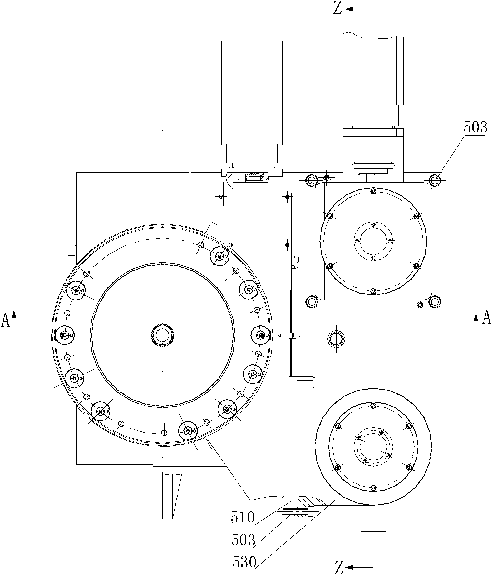
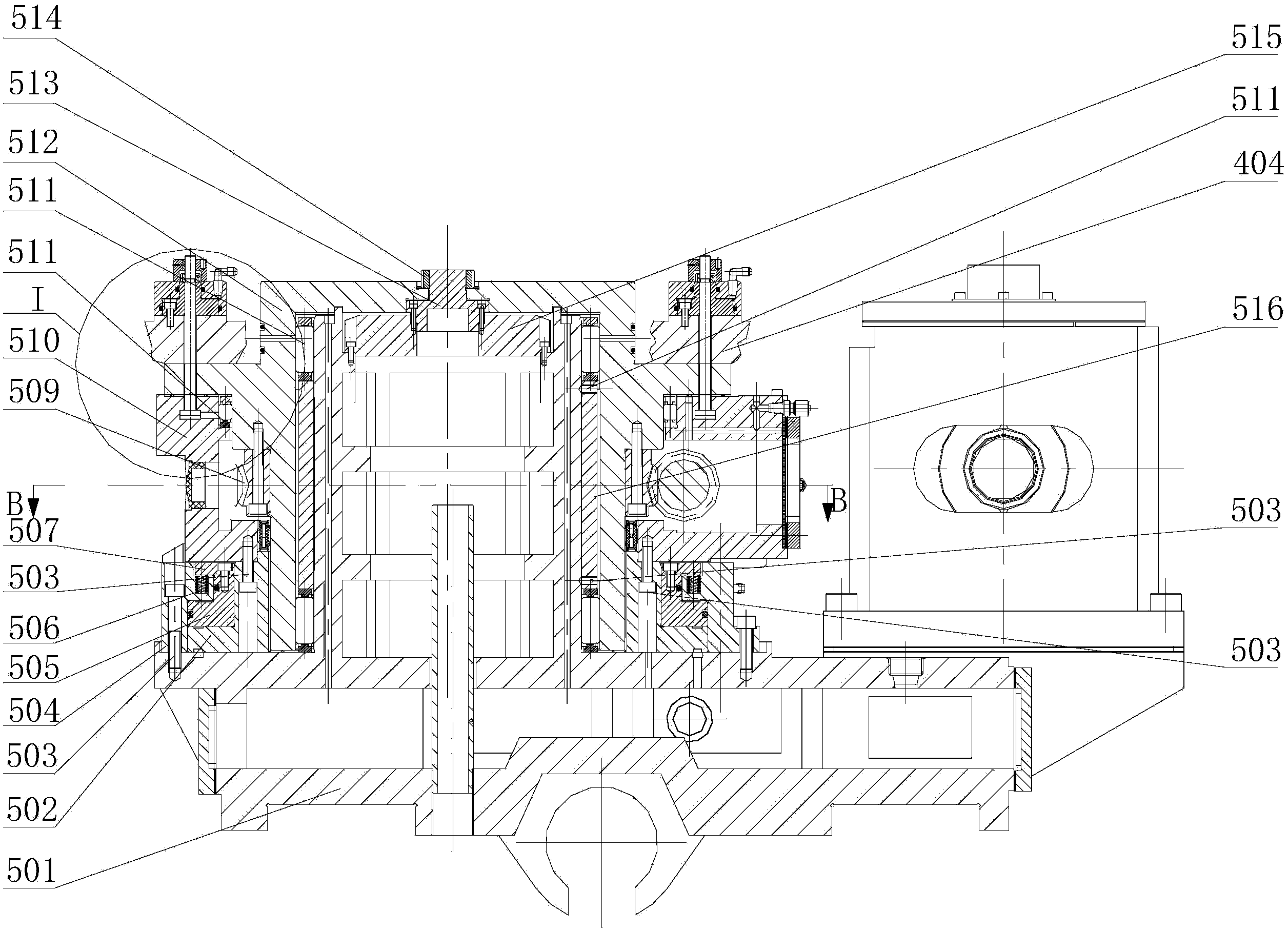
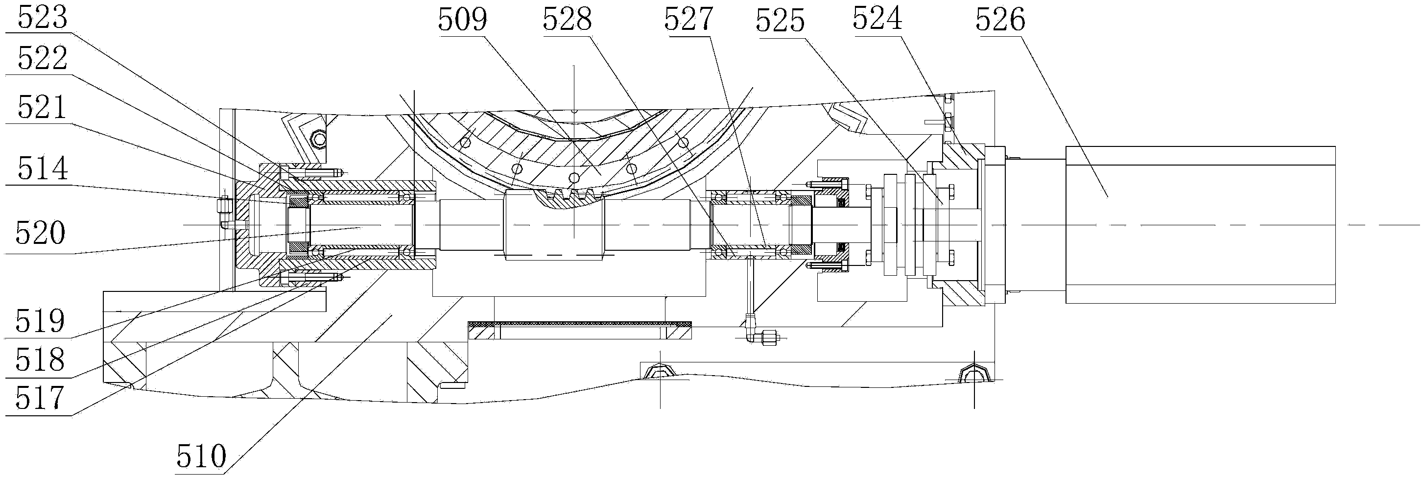
[0024] see Figure 1-Figure 5 , the turntable transmission device of the CNC spiral bevel gear milling machine, including the feed slide 501 and the turntable base 510, and also includes the worm gear bottom sleeve 512 for driving the turntable to rotate. The turntable swing lever mechanism, the second clamping c...


PUM


Abstract

The invention relates to a rotary table transmission device of a numerical control spiral bevel gear milling machine. The rotary table transmission device comprises a feeding sliding plate and a rotary table base and is characterized by further comprising a worm gear bottom sleeve, a worm and gear pair, a rotary table oscillating bar mechanism, a second clamping oil cylinder, a first clamping oil cylinder and a supporting base, wherein the worm gear bottom sleeve and the worm and gear pair are used for driving a rotary table to rotate. The worm gear bottom sleeve is supported on the rotary table base, a worm gear is fixedly installed on the worm gear bottom sleeve, and the lower end of the rotary table base is supported on the top surface of the feeding sliding plate through a first flange plate. The rotary table oscillating bar mechanism is fixedly installed on the top surface of the feeding sliding plate. The supporting base is fixedly installed on the rotary table base. A worm of the worm and gear pair is fixedly installed on the rotary table base in a supporting mode. The rotary table transmission device has the advantages that workpiece boxes needed by rough machining or finish machining of workpieces can be separated in a rotating mode, unnecessary abrasion is reduced, precision of finishing machining is improved, besides, requirements for machining two kinds of tooth gears of a user can be met, the structural design is reliable, rigidity is good, the precision is high, and low-speed crawling does not exist.

Description

technical field [0001] The invention belongs to the technical field of bevel gear processing machine tools, in particular to a turntable transmission device of a numerically controlled spiral bevel gear milling machine. Background technique [0002] The design of the spiral bevel gear of the automobile drive axle mainly adopts two kinds of teeth: tapered teeth and cycloidal teeth. Tapered tooth is a traditional main processing method, which has been widely used at home and abroad for a long time. In recent years, the design calculation and processing adjustment of the cycloid gear have been greatly simplified, and the adjustment of the contact area is also simpler and faster, and the bearing capacity of the cycloid gear is also higher. In the automotive industry at home and abroad, cycloid gears are more and more widely used. Therefore, machine tools that can process both tapered teeth and cycloid teeth are becoming more and more popular. For the full CNC (cross axis) gea...

Claims


Application Information

Patent Timeline
IPC IPC(8): B23Q5/22B23F23/00
CPCB23F9/08B23Q5/34B23Q5/36B23Q5/40
Inventor 沈凤美陈洁柴宝连吴杰王威刘德全
Owner 天津第一机床有限公司
Why Eureka
Try Eureka