Vehicle suspension units and interconnection suspension system

A vehicle suspension and suspension system technology, applied in the field of interconnected suspension systems, can solve the problems of vehicle occupant discomfort, large chassis space, reduced riding comfort, etc., and achieve the effect of convenient vehicle height adjustment

Active Publication Date: 2014-02-19
常州万安汽车部件科技有限公司
View PDF10 Cites 11 Cited by
  • Summary
  • Abstract
  • Description
  • Claims
  • Application Information

AI Technical Summary

Problems solved by technology

But its disadvantages are: as the suspension design tends to be more comfortable, the reduced vertical stiffness and pitch stiffness will lead to: 1. The probability of the suspension anti-collision limiter being broken down is greatly increased, causing the vehicle The occupants feel uncomfortable; 2. The head-up and nodding phenomena during rapid acceleration and braking obviously lead to excessive changes in front and rear tire loads, which affect acceleration and braking performance, that is, prolonged acceleration time and emergency braking distance, and changes in sight lead to safety risks, and worsened ride comfort
The disadvantage is that doubling the number of hydraulic cylinders increases the number of mounting brackets and occupies more chassis space, which increases the unsprung mass accordingly and restricts the seating space in the car; and the excessive pitch stiffness, in the absence of a certain pitch damping Under certain circumstances, when the front wheels of the vehicle pass over obstacles, the impact of the road surface will be transmitted to the rear wheels, thereby reducing the ride comfort

Method used


Image

  • Vehicle suspension units and interconnection suspension system
  • Vehicle suspension units and interconnection suspension system
  • Vehicle suspension units and interconnection suspension system

Examples


Embodiment Construction

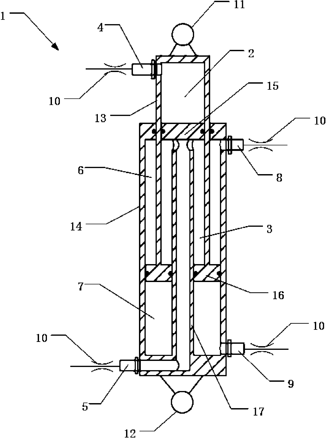
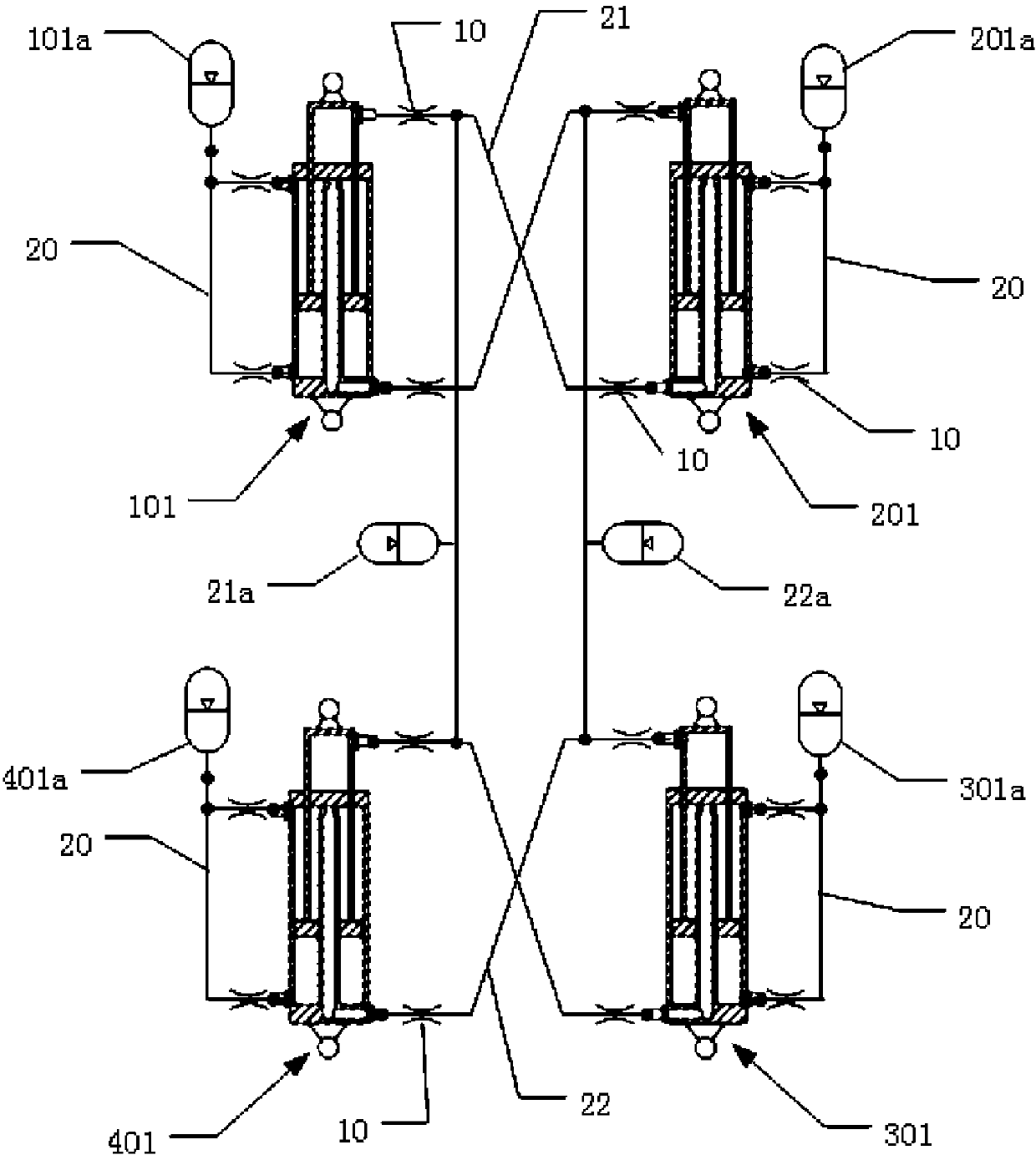
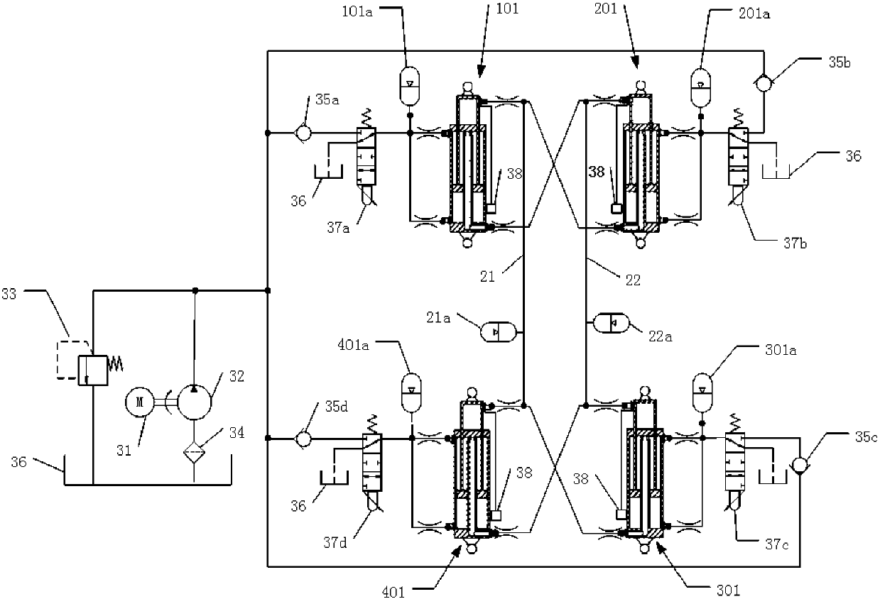
[0046] In order to have a clearer understanding of the technical features, purposes and effects of the present invention, the specific implementation manners of the present invention will now be described in detail with reference to the accompanying drawings.

[0047] Embodiments of the vehicle suspension unit and interconnected suspension system of the present invention are described in detail below, examples of which are shown in the accompanying drawings, wherein like or similar reference numerals designate like or similar elements or have like or similar elements throughout. functional components.

[0048] In describing the vehicle suspension unit and interconnected suspension system of the present invention, it is to be understood that the terms "front", "rear", "upper", "lower", "upper end", "lower end", "upper ", "Lower" and other indicated orientations or positional relationships are based on the orientations or positional relationships shown in the drawings, and are o...


PUM


Abstract

The invention relates to vehicle suspension units and an interconnection suspension system. Each vehicle suspension unit comprises an outer cylinder barrel and an inner cylinder barrel, wherein a hollow piston rod is arranged in the outer cylinder barrel, the upper end of the hollow piston rod is provided with an inner piston, and the inner piston is arranged in the inner cylinder barrel; the lower end of the inner cylinder barrel is provided with an annular outer piston, and the annular outer piston is arranged in an annular cavity formed between the outer cylinder barrel and the hollow piston rod; the inner cylinder barrel is provided with an inner cylinder upper oil opening and an inner cylinder lower oil opening, and the outer cylinder barrel is provided with an outer cylinder upper oil opening and an outer cylinder lower oil opening. The vehicle suspension units can play a role of elastic supporting and a role of damping at the same time, and a plurality of the vehicle suspension units can form the driven or semi-driving interconnection suspension system. The suspension system can be independently optimized according to different performance requirements, and the contradiction between comfortableness and operation stability of a traditional suspension system is greatly eliminated or relieved. In addition, by means of the interconnection suspension system, the vehicle height adjustment can be conveniently carried out, and the stiffness performance of a suspension can not be affected.

Description

technical field [0001] The present invention relates to a vehicle suspension unit and an interconnected suspension system having the suspension unit. Background technique [0002] In general, a two-axle four-wheel vehicle suspension system provides vertical, pitch, roll, and torsional stiffness and damping to the vehicle body. Vehicle comfort and tire grip require smaller suspension vertical and torsional stiffness, and vehicle lateral and longitudinal operational stability require higher suspension roll and pitch stiffness. As a traditional four-wheel independent suspension system, there are contradictions between different requirements, and it is often necessary to make a compromise between the two when designing the suspension. [0003] The transverse stabilizer bar, also known as the anti-roll bar, can provide high roll stiffness without affecting the vertical stiffness and pitch stiffness, but at the same time increase the torsional stiffness, which will greatly reduce...

Claims


Application Information

Patent Timeline
IPC IPC(8): B60G21/06B60G15/00
Inventor 徐光中张农
Owner 常州万安汽车部件科技有限公司
Why Eureka
Try Eureka