Wave-current hybrid drive micro power generation and energy storage system and method for ocean subsurface buoy
An energy storage system and hybrid drive technology, applied in buoys, current collectors, motor vehicles, etc., can solve the problems of limited power supply capacity of batteries, waste of manpower and material resources, troublesome battery replacement, etc., to achieve compact device structure, reduce damage rate, reduce The effect of weight
- Summary
- Abstract
- Description
- Claims
- Application Information
AI Technical Summary
Problems solved by technology
Method used
Image
Examples
Embodiment 1
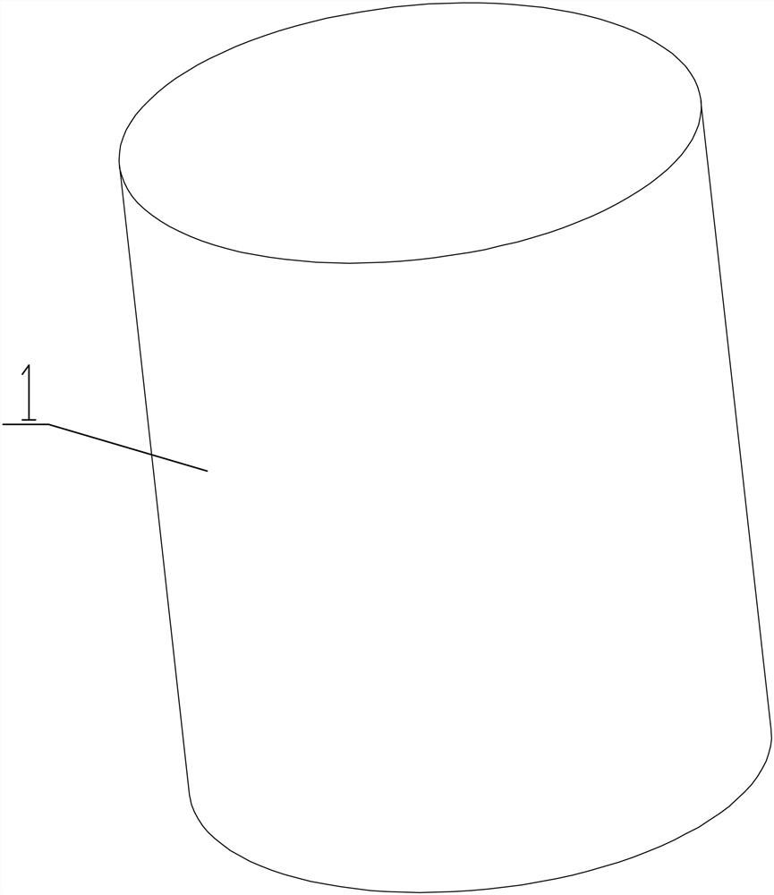
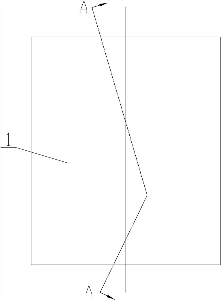
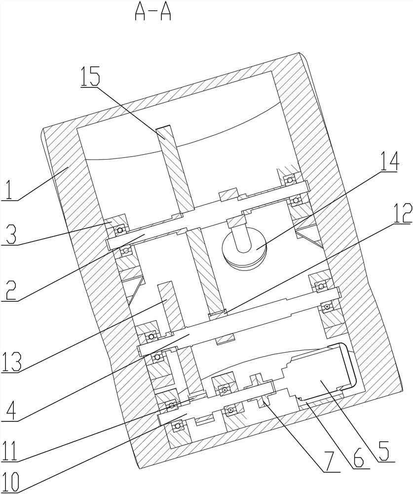
[0037] like Figure 1-9 As shown, a wave-current hybrid-driven micro power generation and energy storage system for marine submersible targets, which includes a driving device, a gear speed-increasing mechanism, and an AC power conversion and energy storage system. The driving device includes a box body 1 and a swaying pendulum 14. The box body 1 has a closed inner cavity. Pendulum 14. The AC power conversion and energy storage system includes an AC generator 5 , a battery power access circuit and a battery 8 , which are fixed in the box 1 and connected to the output shaft 10 of the gear speed increasing mechanism. The above-mentioned device is installed inside the submersible buoy, and inputs a certain electric power to the battery to supplement the electricity, and maintains the submarine buoy to work for a long time. In the specific use process, the system is installed inside the submersible target, and the submersible target vibrates under the excitation of waves or curr...
Embodiment 2
[0042] A method for wave-current power generation by a wave-current hybrid driving micro-power generation and energy storage system for an ocean submersible target, comprising the following steps:
[0043] Step 1: Install the system inside the submersible target, and the submersible target vibrates under the excitation of waves or currents;
[0044] Step 2: The submersible mark drives the box body 1 to move, the box body 1 drives the swing pendulum 14 to swing, and the swing of the swing pendulum 14 drives the gear increasing mechanism to rotate;
[0045] Step 3: Increase the input speed and drive the alternator 5 through the gear speed increasing mechanism;
[0046] Step 4: The electricity generated by the alternator 5 passes through the rectifier circuit 16, the filter capacitor 17, and the voltage regulator tube 18 to generate the required stable voltage and current. Whether the light-emitting diode 19 is on can reflect whether there is electricity, and then passes through ...
PUM
 Abstract
Description
Claims
Application Information
 - R&D
- Intellectual Property
- Life Sciences
- Materials
- Tech Scout
- Unparalleled Data Quality
- Higher Quality Content
- 60% Fewer Hallucinations
Browse by: Latest US Patents, China's latest patents, Technical Efficacy Thesaurus, Application Domain, Technology Topic, Popular Technical Reports.
© 2025 PatSnap. All rights reserved.Legal|Privacy policy|Modern Slavery Act Transparency Statement|Sitemap|About US| Contact US: help@patsnap.com


