

Novel energy-saving gas burner
A gas burner, a new type of technology, applied in the direction of gas fuel burners, burners, combustion methods, etc., can solve the problems of insufficient combustion, low power, floating fire, etc.
Inactive Publication Date: 2014-02-19
徐东
View PDF6 Cites 1 Cited by
- Summary
- Abstract
- Description
- Claims
- Application Information
AI Technical Summary
Problems solved by technology
[0002] The combustion method of traditional stoves is mainly diffusion combustion. The biggest disadvantages of this kind of combustion are insufficient combustion, low power, low thermal efficiency, excessive carbon emissions, the need to set dampers, and the artificial control of the mixing ratio of gas and air, which is difficult to accurately control
There are also a small number of stoves that use a semi-premixed combustion method, which can easily lead to flame separation, tempering, and sparks. If the gas pressure changes, it cannot be used normally.
Method used
View moreImage
Smart ImageViewing Examples

Examples
Embodiment Construction
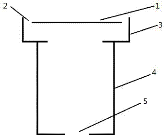
[0006] The gas burner has a round pipe gas supply pipe 4 that is uniform up and down. The lower part of the gas supply pipe 4 is an air inlet 5. The upper end of the gas supply pipe 4 is placed with three flamethrowers 3 that are tangential to the diameter of the garden. The flamethrower top plate 1 is located on the flamethrower 3. In the middle position, there is a groove 2 between the flamethrower 3 and the top plate 1 of the flamethrower, and the groove 2 communicates with the air inlet 5 up and down.
Login to View More PUM
 Abstract
The invention discloses a novel energy-saving gas burner. According to the novel energy-saving gas burner, defects of burners in the prior art in the process of burning are overcome. Compared with a traditional stove burning distributor, the novel energy-saving gas burner has the advantages of being larger in power, more sufficient in burning, higher in heat efficiency, free from influences of gas sources and air pressure, free of lifted frame and flying fire, high in durability, low in manufacturing cost, friendly to environment and capable of saving energy. To overcome the defects in the background technology, the novel energy-saving gas burner is simple and reasonable in structure, and convenient to operate. According to the novel energy-saving gas burner, the structure of the original burner is changed, and therefore the heat efficiency is improved greatly and carbon emission is reduced.
Description
technical field [0001] The invention relates to a core component of a cooker structure, in particular to a gas combustion burner. Background technique [0002] The combustion method of traditional stoves is mainly diffusion combustion. The biggest disadvantages of this kind of combustion are insufficient combustion, low power, low thermal efficiency, excessive carbon emissions, the need to set dampers, and the artificial control of the mixing ratio of gas and air, which is difficult to accurately regulation. There are also a small number of stoves that use a semi-premixed combustion method, which can easily lead to flame separation, tempering, and sparks. If the gas pressure changes, it cannot be used normally. This burner changes the structure of the previous burner and makes up for the disadvantages of the previous cooking stoves. Compared with the traditional stove burner, it has greater power, more complete combustion, higher thermal efficiency, is not affected by ch...
Claims
Login to View More Application Information
Patent Timeline
 IPC IPC(8): F23D14/46
Inventor徐东
Owner徐东