Eureka AIR delivers breakthrough ideas for toughest innovation challenges, trusted by R&D personnel around the world.

Time grating linear displacement sensor based on alternating light fields

A linear displacement and sensor technology, applied in the field of sensors, can solve problems such as low production efficiency, high power consumption, and poor machinability of magnetic materials, and achieve the effects of easy installation, low cost, and high precision

Active Publication Date: 2014-02-19
CHONGQING MINSHENG SENSING TECH CO LTD
View PDF6 Cites 17 Cited by
  • Summary
  • Abstract
  • Description
  • Claims
  • Application Information

AI Technical Summary

Problems solved by technology

The magnetic field time grating adopts the principle of electromagnetic induction for measurement. Due to the poor machinability of the magnetic permeable material, the production process needs to be wound, so its production efficiency is low. In addition, it requires a large excitation power to drive the stator coil, resulting in high power consumption. Big
The electric field time grating adopts the principle of alternating electric field coupling for measurement. For example, the patent with the announcement number CN102288100B and the name "A time grating linear displacement sensor based on alternating electric field" adopts semiconductor processing technology and has high manufacturing accuracy and consistency. Good, but because the electric field signal is in a divergent state in the air gap, and it requires the parallel installation distance between the fixed-length substrate and the probe substrate to be as small as possible, the installation and production of the sensor are difficult

Method used


Image

  • Time grating linear displacement sensor based on alternating light fields
  • Time grating linear displacement sensor based on alternating light fields
  • Time grating linear displacement sensor based on alternating light fields

Examples


Embodiment Construction

[0024] The present invention will be further described below in conjunction with accompanying drawing.

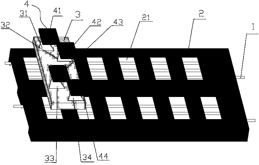
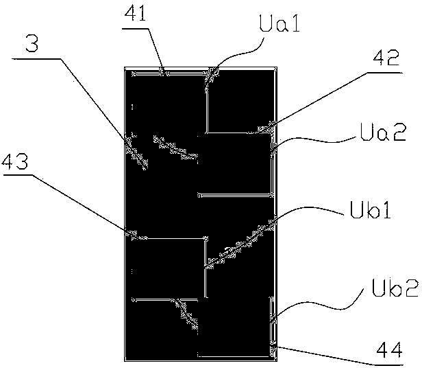
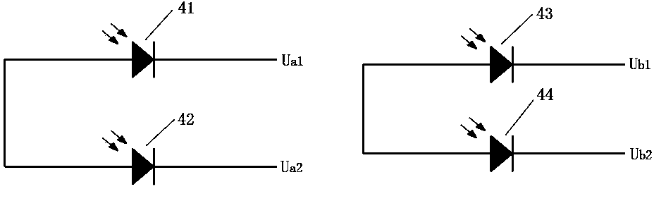
[0025] Such as figure 1 , figure 2 , image 3 , Figure 4 , Figure 5 The shown time grating linear displacement sensor based on alternating light field includes a fixed plate 2, a moving plate 3, four photosensitive receiving units 4 and two groups of light-emitting devices, and the fixed plate 2 and the moving plate 3 are relatively parallel to each other. , and leave a gap of 0.4mm, the four photosensitive receiving units 4 adopt four SMD photosensitive diodes of the same type (also can use the same type of photocell), the light-emitting device is a side-light optical fiber 1, and a set of side-light optical fibers 1 is fixed At the upper part behind the fixed pole plate 2, another group of side-light optical fibers 1 is fixed on the lower part behind the fixed pole plate 2, and the two groups of side-light optical fibers 1 are separated by a boss 22 covered with a ...


PUM


Abstract

The invention discloses a time grating linear displacement sensor based on alternating light fields. The sensor comprises a static pole plate and a moving pole plate, wherein each of the upper and low portions of the static pole plate includes a row of uniformly-distributed square transparent surfaces of the static pole plate, each of the rear upper and lower portions of the static pole plate is equipped with a set of luminescent devices, each of the upper and lower portions of the moving pole plate includes two semi-sinusoid transparent surfaces of the moving pole plate, four photosensitive reception units are fixed on the moving pole plate, and the transparent surfaces of the moving pole plate are covered with photoelectric reception surfaces of the photosensitive reception units. The two sets of the luminescent devices respectively provide alternating light fields, the moving pole plate moves relative to the static pole plate, the four photosensitive reception units output electric signals, two light-field coupling signals are obtained after differencing, a path of travelling wave signals Uo is synthesized via an addition circuit, the path of travelling wave signals Uo is shaped and phase-compared with a path of reference signals Ur, and the linear displacement value of the moving pole plate relative to the static pole plate is obtained via clock interpolation and scale conversion. The time grating linear displacement sensor based on alternating light fields is high in precision, low in power consumption, low in cost and easy to install and prepare.

Description

technical field [0001] The invention relates to a sensor, in particular to a sensor for precision linear displacement measurement in the optical field. Background technique [0002] In the field of optics, the sensing technologies used for precision linear displacement measurement mainly include: grating and laser interferometer. [0003] Gratings measure displacement by counting the number of moiré fringes. It adopts precision mechanical subdivision technology to process very dense and equally spaced grating lines on the surface of the indicator grating and scale grating, and stacks the indicator grating and scale grating together, leaving an appropriate small gap in the middle, and making the two gratings Keep a small angle between the reticle lines, the reticle lines of the two gratings intersect, and irradiate with a light source of constant light intensity in the vertical direction of many intersecting reticle lines, and the light passes through the gap where the retic...

Claims


Application Information

Patent Timeline
Patent Type & Authority Applications(China)
IPC IPC(8): G01B11/02
CPCG01D5/34746G01B11/14G01D5/34715G01D5/36
Inventor 付敏刘小康彭东林夏豪杰朱革
Owner CHONGQING MINSHENG SENSING TECH CO LTD
Why Eureka
Eureka Blog
Learn More