Scintillation crystal array detector and PET-MR system using the detector

A scintillation crystal array and scintillation crystal technology, which are applied to instruments, measuring devices, scientific instruments, etc., can solve the problems of reduced light conversion rate, wear and tear of scintillation crystal array detectors, affecting image quality, etc., so as to ensure image quality and reduce reflections. The number of times, the effect of improving the receiving efficiency

Active Publication Date: 2014-02-19
SHANGHAI UNITED IMAGING HEALTHCARE
View PDF2 Cites 17 Cited by
  • Summary
  • Abstract
  • Description
  • Claims
  • Application Information

AI Technical Summary

Problems solved by technology

Since the scintillation crystals 31 of the scintillation crystal array 21 are arranged in a cuboid shape, the fluorescence of a specific wavelength range of 400nm-550nm induced in the scintillation crystals by th

Method used


Image

  • Scintillation crystal array detector and PET-MR system using the detector
  • Scintillation crystal array detector and PET-MR system using the detector
  • Scintillation crystal array detector and PET-MR system using the detector

Examples


Embodiment Construction

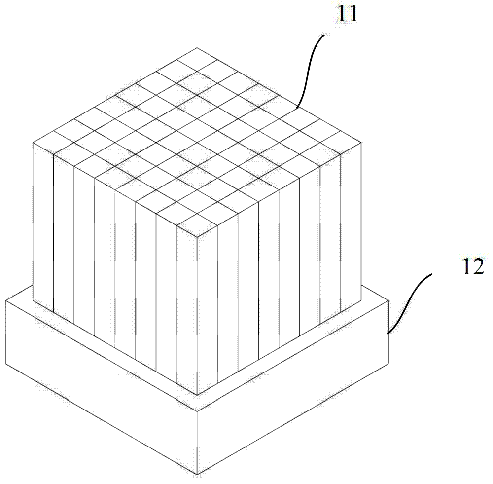
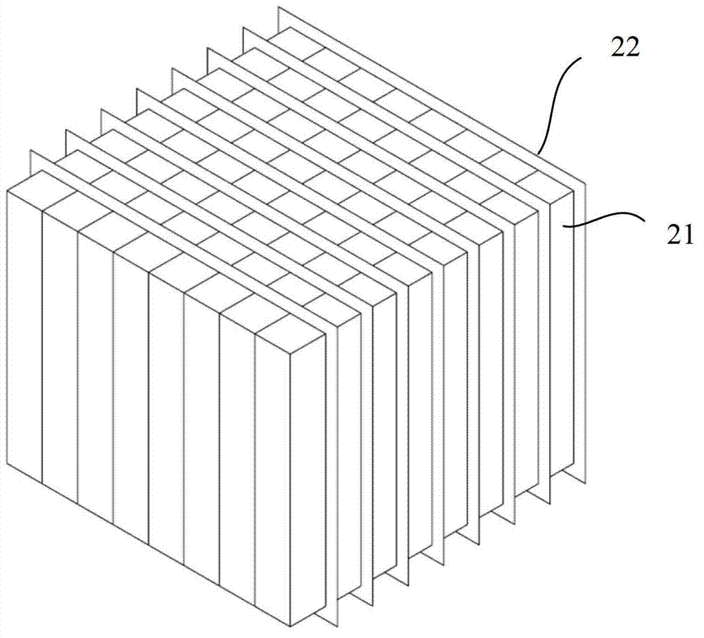
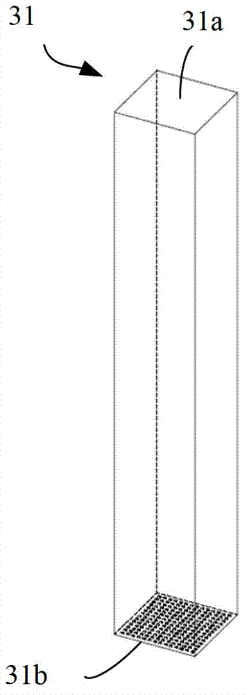
[0030] Such as Figure 4 to Figure 6 As shown, the scintillation crystal array detector 400 of the present invention is used in a PET imaging system or a PET-MR imaging system, which includes a scintillation crystal array 410 and an avalanche photodiode array 420 coupled with the scintillation crystal array 410 . The scintillation crystal array 410 consists of rows ( Figure 4 x-direction) and columns ( Figure 4 It is composed of a plurality of scintillation crystals 401 on the middle y direction). Each scintillation crystal 401 has a top surface, a bottom surface opposite to the top surface, and a plurality of side surfaces connecting the top surface and the bottom surface. The avalanche photodiode array 420 is in the shape of a sheet, and is used for coupling with scintillation crystals (such as 401A-401H) located in the same row. Avalanche photodiode array 420 may include multiple Figure 5 Avalanche photodiode sub-array 421 is shown. Such as Figure 5 As shown, each...


PUM


Abstract

The invention provides a scintillation crystal array detector which can be used to increase receiving efficiency of visible light and is used for a PET-MR imaging system. The scintillation crystal array detector comprises a scintillation crystal array and an avalanche photodiode array. The avalanche photodiode array comprises a plurality of avalanche photodiode subarrays. Each avalanche photodiode subarray comprises a plurality of avalanche photodiodes. The scintillation crystal array comprises a plurality of scintillation crystals. Each scintillation crystal possesses a coupling surface which is coupled with one of the plurality of avalanche photodiode subarrays and a plurality of adjacent surfaces which are adjacent to the coupling surface. At least one adjacent surface of the plurality of adjacent surfaces in the scintillation crystals and the coupling surface form an acute angle. Reflex numbers of the visible light in the scintillation crystals can be reduced. The receiving efficiency of the visible light is increased so that image quality of the PET-MR imaging system during image reconstruction is further guaranteed.

Description

technical field [0001] The present invention relates to a scintillation crystal detector used in PET (Positron Emission Computed Tomography, positron emission computed tomography) imaging system, in particular to a scintillation crystal array detector used in PET-MR imaging system and using the PET-MR system with scintillation crystal array detector. Background technique [0002] PET-MR imaging system (Positron-Emission Computed Tomography-Magnetic Resonance Imaging System) is a combination of PET (Positron-Emission Computed Tomography, Positron-Emission Tomography) and MR (Magnetic Resonance, Nuclear Magnetic Resonance Scanner) technology A molecular-level functional imaging plus structural imaging system, which uses the high resolution of high-field superconducting MR and the high sensitivity of PET to realize the complementarity of anatomical structure imaging and functional imaging, and realize the functional imaging of MR The powerful combination and cross-validation w...

Claims


Application Information

Patent Timeline
IPC IPC(8): G01T1/202
Inventor 赵太泽
Owner SHANGHAI UNITED IMAGING HEALTHCARE
Why Eureka
Try Eureka