Free-form surface imaging optical system

An imaging optics, free technology, applied in the field of space optics, can solve the problems affecting the use range of space cameras, large imaging distortion, image deformation, etc., to achieve the effects of small imaging distortion, reduced wave band drift, and reasonable spacing design

Inactive Publication Date: 2014-02-19
CHANGCHUN INST OF OPTICS FINE MECHANICS & PHYSICS CHINESE ACAD OF SCI
View PDF4 Cites 18 Cited by
  • Summary
  • Abstract
  • Description
  • Claims
  • Application Information

AI Technical Summary

Problems solved by technology

In addition, the imaging distortion of the existing off-axis reflective system is too large, and the image formed by the system is seriously deformed, which affects the scope of use of the space camera.
[0004] In 2012, the inventor obtained the invention patent of super

Method used


Image

  • Free-form surface imaging optical system
  • Free-form surface imaging optical system
  • Free-form surface imaging optical system

Examples


Embodiment Construction

[0014] The present invention will be described in further detail below in conjunction with the accompanying drawings and embodiments.

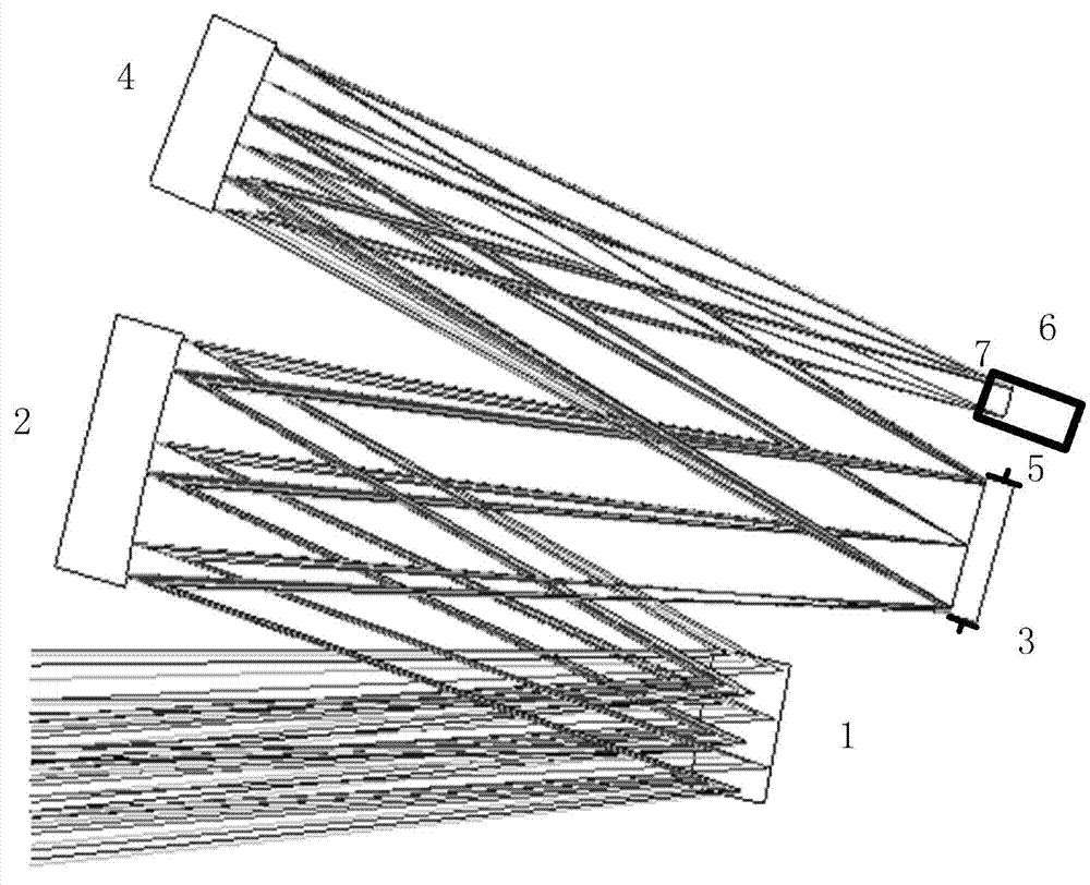
[0015] figure 1 Shown is a schematic structural view of the free-form surface imaging optical system provided by the embodiment of the present invention. The technical scheme adopted in the present invention is: the optical system adopts the structure form of a total reflection system, adopts four reflectors, reflector 1 has a negative focal power, reflectors 2, 3, and 4 are free-form surfaces, and the optical axes of the four reflectors None of them coincide with the optical axis of the system, and the optical axis of the system is deflected every time it is reflected.

[0016] Concrete freeform surface imaging optical system described in the present invention is made up of first reflector 1, the second reflector 2, the 3rd reflector 3, the 4th reflector 4 and aperture stop 5, and multi-spectral array detection element 6 composition.

[00...


PUM


Abstract

The invention discloses a free-form surface imaging optical system. The free-form surface imaging optical system comprises a first reflector, a second reflector, a third reflector, a fourth reflector, an aperture diaphragm and a detector. A target is irradiated on the second reflector after being reflected by the first reflector, is irradiated on the third reflector after being reflected by the second reflector, is irradiated on the fourth reflector after being reflected by the third reflector, and finally is irradiated on the image plane of the detector after being reflected by the fourth reflector. The aperture diaphragm coincides with the third reflector in position. The first reflector is a long-strip-shaped spherical reflector of which the focal power is negative. The second reflector is a free-form surface reflector of which the focal power is positive. The third reflector is a free-form surface reflector of which the focal power is negative. The fourth reflector is a free-form surface reflector of which the focal power is positive. A camera with the free-form surface imaging optical system adopted is huge in view field and small in distortion, and can achieve multi-spectrum imaging. The free-form surface imaging optical system can be applied to the field of aeronautics and astronautics photo-electronic imaging.

Description

technical field [0001] The invention relates to the technical field of space optics, in particular to a free-form surface imaging optical system in space optics. Background technique [0002] The invention uses a multi-spectral linear array photodetector as an imaging receiver with a free-form surface, super-large field of view, total reflection, and multi-spectral imaging space camera optical system, which is obtained in the fields of ground reconnaissance, remote sensing, and detection in aviation and aerospace space. High-definition photos can be widely used in civil, national defense, military and other fields. [0003] The off-axis three-reflection optical system camera currently used has a limited field of view tolerance. At present, the largest off-axis three-reflection optical system in China has a field of view of 17°. In addition, the imaging distortion of the existing off-axis reflective system is too large, and the image formed by the system is seriously deforme...

Claims


Application Information

Patent Timeline
IPC IPC(8): G02B17/06G01J3/02
Inventor 张新王灵杰
Owner CHANGCHUN INST OF OPTICS FINE MECHANICS & PHYSICS CHINESE ACAD OF SCI
Why Eureka
Try Eureka