Substrate integrated waveguide ferrite switch

A substrate-integrated waveguide and ferrite technology, applied in waveguide-type devices, electrical components, circuits, etc., can solve the problems of complex processing, narrow switching bandwidth, large switching volume, etc., and achieve low width requirements and strong heat dissipation capability. , the effect of high isolation

Active Publication Date: 2014-02-19
成都宁锦威通信技术有限公司
View PDF3 Cites 7 Cited by
  • Summary
  • Abstract
  • Description
  • Claims
  • Application Information

AI Technical Summary

Problems solved by technology

But this type of switch has the following problems: 1) To change the cut-off frequency of the waveguide through different magnetic biases, it is necessary to ensure that the switch works below the ferrite gyromagnetic resonance point, and its variable range is limited, resulting in a narrow switch bandwidth; 2) must Under the magnetic bias, the ferrite permeability increases with the frequency, and its change gradually decreases, resulting in a narrower high-frequency operating bandwidth of the switch; 3) A thinner ferrite block is required, and a thinner ferrite block is in the In addition, the ability to change the cutoff frequency of the waveguide is weak after magnetic bias, so its length needs to be increased to obtain the same bandwidth, resulting in a larger volume of the entire switch; 4) It is difficult to integrate with planar circuits, complex processing, and high cost
Such substrate-integrated waveguide switches suffer from similar drawbacks to waveguide switches due to similar operating principles
At the same time, since the substrate-integrated waveguide is a dielectric-filled structure, it is necessary to dig a rectangular long groove on the dielectric substrate to facilitate the placement of the ferrite sheet during the design of the switch. The process maturity is low, the processing is difficult, and it is difficult to apply at high frequencies.
In addition, the ferrite sheet is placed inside the substrate integrated waveguide, which is not suitable for heat dissipation in high-power applications

Method used


Image

  • Substrate integrated waveguide ferrite switch
  • Substrate integrated waveguide ferrite switch
  • Substrate integrated waveguide ferrite switch

Examples


Embodiment

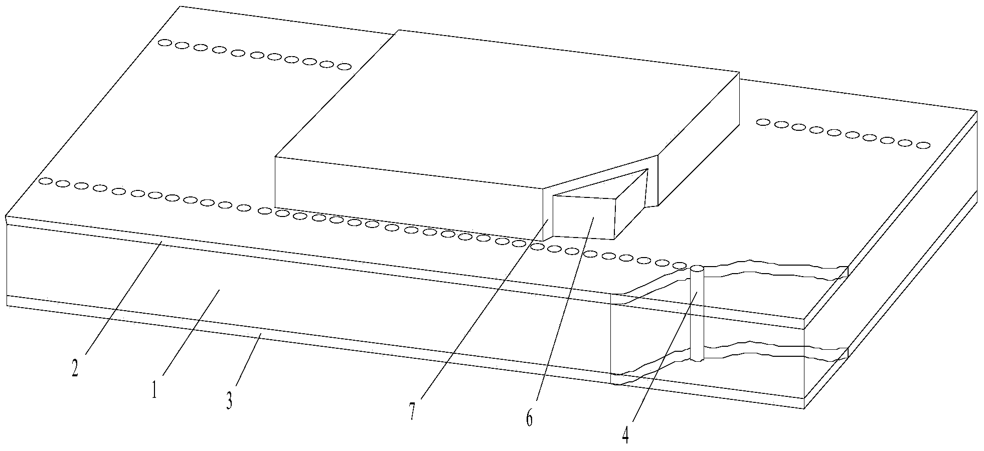
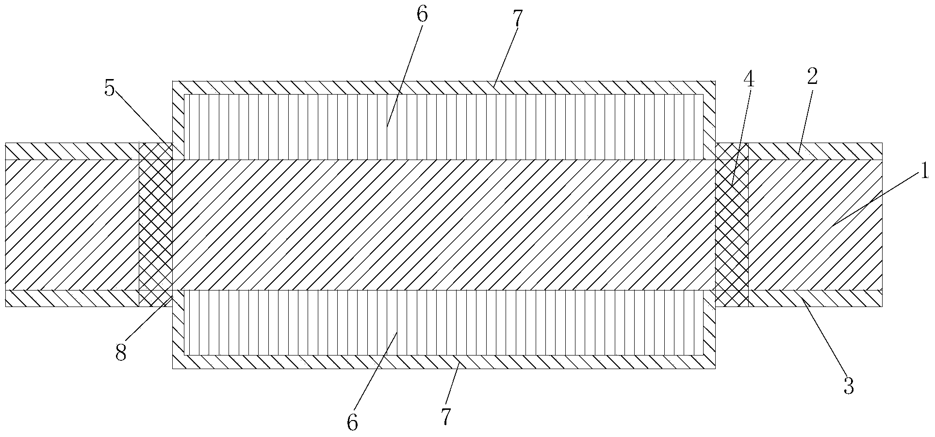
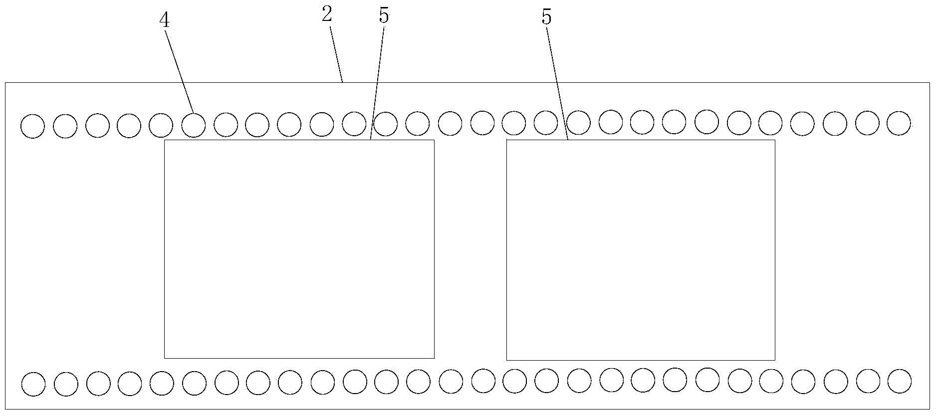
[0022] In this embodiment, the number of ferrite blocks 6 of the substrate-integrated waveguide ferrite switch is two, all of which are installed on the first metal copper clad layer 2, and the structure of the first metal copper clad layer 2 is as follows image 3 As shown, the dielectric constant of the first selected dielectric substrate 1 is 10.2, the thickness is 0.635mm, and the loss tangent is 0.0024; the ferrite block 6 is YIG-1850, the relative dielectric constant is 14.5, and the 3dB line width is 20Oe. Loss tangent 0.0002, saturation magnetization 1850Gs. The width of the substrate integrated waveguide is 8mm, the diameter of the metal through hole is 0.6mm, the distance between the through holes is 1.2mm, the thickness of the ferrite block 6 is 0.8mm, the length is 6mm, and the width is 7.4mm. The distance between the two ferrite blocks 6 is 1mm. 3010Oe. The performance comparison is shown in the table below:

[0023]

[0024] It can be seen from the above tab...


PUM


Abstract

The invention discloses a substrate integrated waveguide ferrite switch which is good in allowance, wide in broadband and relatively high in isolation. The substrate integrated waveguide ferrite switch comprises a medium substrate, wherein the upper surface of the medium substrate is provided with a first metal copper-coated layer, the lower surface of the medium substrate is provided with a second metal copper-coated layer, the medium substrate is provided with two rows of metallization through holes which are parallel to each other, the first metal copper-coated layer is provided with at least one first ferrite installation hole, a ferrite block is arranged in the first ferrite installation hole, and the upper surface and the side surface of the ferrite block are respectively coated with a metal coating. External loading is adopted to replace traditional internal inserting, processing is easier, the requirement for the width of the ferrite block is low, and allowance is good. Meanwhile, the contact area between the ferrite block and the outside is relatively large, and heat dissipation ability is high. Under the same length, the broadband width of the substrate integrated waveguide ferrite switch is greatly larger than that of an existing switch, the isolation is higher, and the substrate integrated waveguide ferrite switch is suitable for being popularized and applied in the technical field of ferrite switches.

Description

technical field [0001] The invention relates to the technical field of ferrite switches, in particular to a substrate-integrated waveguide ferrite switch. Background technique [0002] In 2000, researchers proposed the concept of substrate integrated circuits based on ordinary printed circuit board (PCB) technology, among which the most concerned technology is substrate integrated waveguide. In the past two years, on the basis of sufficient research on the transmission characteristics of substrate-integrated waveguide structures, a variety of ferrite magnetron devices based on substrate-integrated waveguide technology, including switches, have been realized, which has greatly promoted the development of substrate-integrated waveguide technology. new development. At present, broadband and miniaturization are the main development directions of substrate-integrated waveguide magnetic control switches. [0003] The traditional ferrite switch embeds ferrite into the waveguide, ...

Claims


Application Information

Patent Timeline
IPC IPC(8): H01P1/11
Inventor 程钰间黄秋栋
Owner 成都宁锦威通信技术有限公司
Why Eureka
Try Eureka