
Field in-situ continuous low-abundance 13CO2 isotope labeling device and method

An isotope labeling, low-abundance technology, which can be used in measurement devices, horticultural methods, botanical equipment and methods, etc. Effect

Inactive Publication Date: 2014-02-26
NORTHEAST INST OF GEOGRAPHY & AGRIECOLOGY C A S
View PDF4 Cites 18 Cited by
  • Summary
  • Abstract
  • Description
  • Claims
  • Application Information

AI Technical Summary

Problems solved by technology

[0004] The present invention aims to solve the problem that the traditional device or method for marking C elements on plants adopts the pulse type marking method, the marking accuracy is low, and the cost is high. The present invention provides a field in-situ continuous low-abundance 13 CO 2 Isotope labeling device and method

Method used


Image

  • Field in-situ continuous low-abundance 13CO2 isotope labeling device and method

Examples


specific Embodiment approach 1

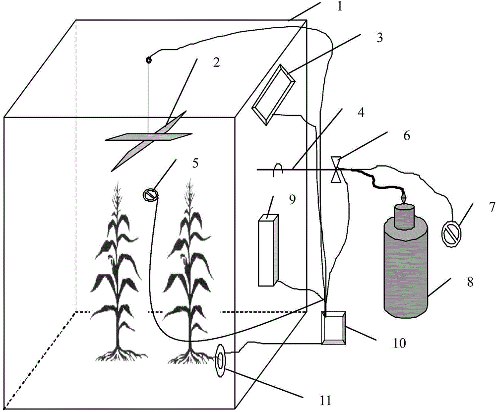
[0015] Specific embodiment one: see figure 1 Explain this embodiment, a field in situ continuous low abundance described in this embodiment 13 CO 2 Isotope marking device, which includes marking box 1, fan 2, air conditioner 3, burner 4, CO 2 The measuring controller 5, the oxygen cylinder 7, the liquefied gas cylinder 8, the dehumidifier 9, the automatic control system 10 and the humidifier 11; the marking box 1 is a bottom-opened box, and the side wall of the marking box 1 is provided with A through hole, the marking box 1 is a transparent box body, the burning end of the burner 4 penetrates the through hole of the marking box 1 to extend into the marking box 1, and the end of the burner 4 is at the same time as the liquefied gas cylinder The air outlet of 8 is connected with the air outlet of the oxygen cylinder 7. The combustion end of the burner 4 is provided with an electronic lighter 6; the fan 2 is fixed at the top middle position in the marking box 1, and the air condit...

specific Embodiment approach 2

[0016] Specific implementation manner 2: see figure 1 Description of this embodiment, this embodiment and the first embodiment of a field in situ continuous low abundance 13 CO 2 The difference between the isotope labeling device is that the CO 2 The measuring controller 5 is located in the middle position inside the marking box 1.

specific Embodiment approach 3

[0017] Specific implementation manner three: see figure 1 Description of this embodiment, this embodiment and the specific embodiment 1 or 2, a field in situ continuous low abundance 13 CO 2 The difference of the isotope marking device is that the air conditioner 3 and the dehumidifier 9 are arranged on the same side wall of the marking box 1.


PUM


Abstract

The invention discloses a field in-situ continuous low-abundance 13CO2 isotope labeling device and method, relates to a simulator for detecting crop rhizosphere respiration and labeling plants, and solves the problems of low labeling precision and high cost of a pulse labeling mode of a traditional C element labeling device or method for the plants. A labeling box is a transparent box with a through hole in the side wall, a combustion end of a combustor penetrates the through hole of the labeling box and extends into the labeling box, the tail end of the combustor is simultaneously communicated with a gas outlet of a liquefied gas bottle and a gas outlet of an oxygen bottle, an electronic fire maker is arranged at the combustion end of the combustor, a fan is fixed to the middle of the inner top of the labeling box, an air conditioner is fixed to the upper portion of the side wall of the labeling box, a CO2 measurement and control device and a humidifier are positioned in the labeling box, a dehumidifier is fixed to the lower portion of the side wall of the labeling box, and the fan, the air conditioner, the CO2 measurement and control device, the electronic fire maker, the dehumidifier and the humidifier are controlled by an automatic control system. The device and the method are used for performing continuous low-abundance 13CO2 labeling for crops.

Description

Technical field [0001] The invention relates to a simulation device for detecting crop rhizosphere respiration and marking plants. Background technique [0002] In the past, people usually used high abundance 13 CO 2 For pulsed labeling, few people use high abundance 13 CO 2 Continuous marking, discontinuous marking of crops, high marking cost, backward detection methods, large errors and low precision. Now, with the advancement of science and technology and the increase of greenhouse gases in the atmosphere, people have continuously improved the research methods and methods for the distribution of crop photosynthetic products, and people are soberly aware that the use of continuous 13 CO 2 The importance of labeling, it determines the CO in the fixed atmosphere of crops 2 The ability to affect the ecosystem through redistribution. Therefore, researchers at home and abroad in greenhouse gas and plant physiology 13 CO 2 Marking research is very important. 13 C continuous labeling ...

Claims


Application Information

Patent Timeline
Patent Type & Authority Applications(China)
IPC IPC(8): A01G7/02G01N33/00
Inventor 乔云发苗淑杰高淑杰
Owner NORTHEAST INST OF GEOGRAPHY & AGRIECOLOGY C A S
Learn More