Controllable deformable soft cutter

A tool and tool holder technology, applied in the field of controllable deformation soft tools, can solve the problems of surface scratches, workpiece size errors, lack of surface conformity, etc., and achieve the effect of improving processing efficiency and improving grinding effect.

Active Publication Date: 2014-02-26
杨斌堂
View PDF7 Cites 3 Cited by
  • Summary
  • Abstract
  • Description
  • Claims
  • Application Information

AI Technical Summary

Problems solved by technology

However, the whole tool and the part of the tool tip that is in contact with the workpiece are rigid bodies that do not have the conformity with the surface of the workpiece, and the small feed error of the tool deformation may cause errors in the size of the workpiece or surface scratches; and the tool and The contact of the workpiece is point contact, which cannot realize the smoothing of a large area of ​​the workpiece surface

Method used


Image

  • Controllable deformable soft cutter
  • Controllable deformable soft cutter
  • Controllable deformable soft cutter

Examples


Embodiment 1

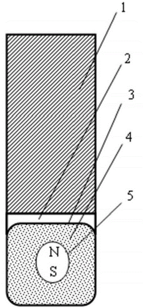
[0046] This embodiment provides a controllable deformable soft tool, including a handle, a functional accessory, and a deformable cutter head, and the deformable cutter head is connected to the handle through a functional accessory; wherein, the deformable cutter head It includes: a sealed and deformed soft shell and a deformation medium arranged inside the sealed and deformed soft shell. The controllable deformable soft tool is connected to the machine tool through the tool handle, and the machine tool drives the tool handle to move, thereby deforming the deformation medium inside the sealed and deformed soft shell, thereby prompting the sealed and deformed soft shell to generate processing force.

[0047] Further, in this embodiment, the deformable cutter head may also include a deformable medium activator mechanism, and the deformable medium activator mechanism interacts with the deformable medium to cause greater deformation of the deformable medium, thereby deforming the s...

Embodiment 2

[0057] Embodiment 2 is a modification example of Embodiment 1.

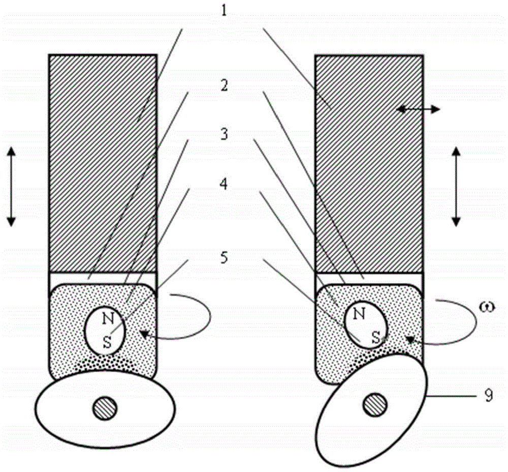
[0058] The mechanism of action of this embodiment and component parts and action process are identical with embodiment 1, as Figure 5 shown. In order to increase the processing effect of large-surface shell workpieces, the deformation medium actuator can be placed outside the sealed deformation soft shell to form an external deformation medium actuator, and the workpiece is placed between the external deformation medium actuator and the seal between deformed soft shells, such as image 3 shown.

[0059] In this embodiment, deformable medium actuators can also be placed inside and outside the sealed and deformed soft shell, that is, the built-in deformed medium actuator arranged inside the sealed and deformed soft shell and the built-in deformed medium actuator set outside the sealed and deformed soft shell The external deformation medium actuator together constitute the deformation medium actuator mechanism, ...

Embodiment 3

[0061] Embodiment 3 is a variation of Embodiment 2.

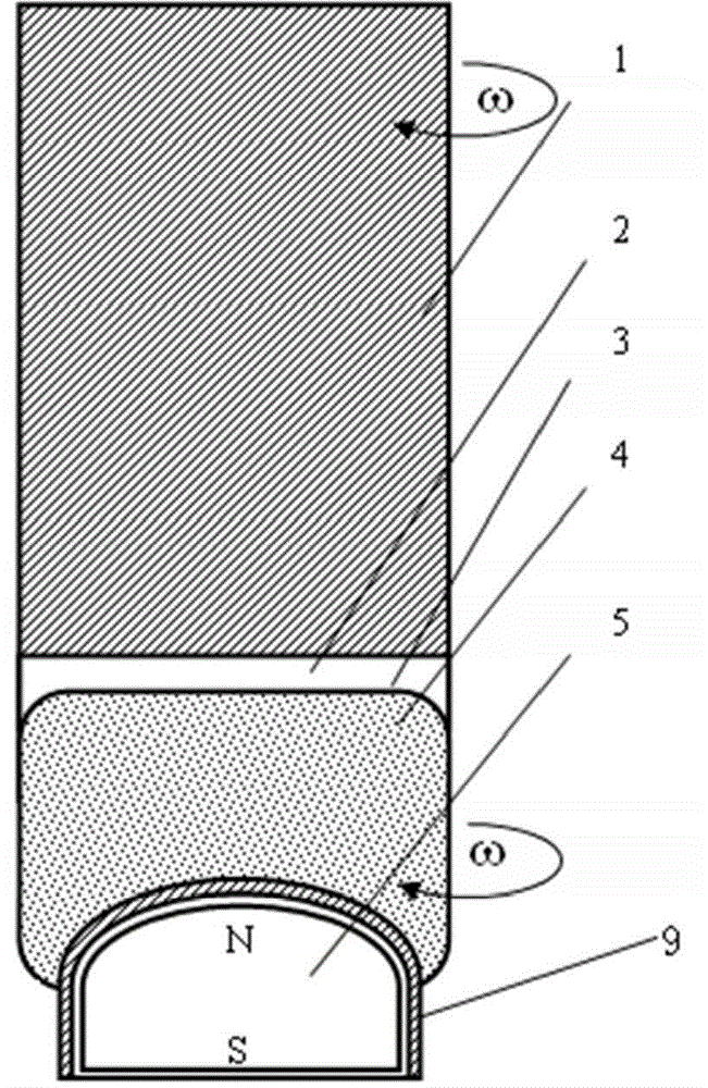
[0062] The action mechanism, components and action process of this embodiment are the same as those of Embodiment 2. In order to increase the magnetic field excitation effect of the deformation medium actuator mechanism, a bearing rotating body is added to the external deformation medium actuator, and the bearing rotating body is a rotating shaft or a ball hinge, such as Figure 6 As shown in the figure, the magnetic pole of the external deformable medium exciter moves with the controllable deformable soft tool through the action of the magnetic field force, so as to achieve a higher efficiency of light under the condition that the magnetic pole of the external deformable medium exciter is always excited by a strong magnetic field. The whole processing process.


PUM


Abstract

The invention discloses a controllable deformable soft cutter which comprises a cutter handle, a function accessory and a deformable cutter bit. The deformable cutter bit is connected with the cutter handle through the function accessory. The deformable cutter bit comprises a sealing deformable soft casing, a deformable medium filled in the sealing deformable soft casing and a deformable medium excitatory mechanism acting with the deformable medium in a mutual mode to enable the sealing deformable soft casing to generate machining force. The sealing deformable soft casing is in contact with a workpiece, the controllable deformable soft cutter can move along with a machine tool, namely translation and rotation with strokes relative to the workpiece, contact friction movement matched with a face type is conducted on a workpiece with a complex face type, and efficient and smooth machining on the surface of the complex workpiece is achieved.

Description

technical field [0001] The invention relates to the technical field of grinding, polishing and deburring processing of non-flat workpiece surfaces, in particular to a controllable deformation soft tool used for high-efficiency processing of the inside and outside of precision optics and finishing devices. Background technique [0002] Traditional cutting tools are rigid and non-deformable cutting tools, and the surface shape and size of the workpiece are guaranteed by the feed distance of the cutting tool relative to the workpiece. For processing devices with precise shape or precise size requirements, it is required that the machine tool that drives the tool movement can achieve precision or ultra-precision feeding capabilities to ensure the machining accuracy of the workpiece. However, this will greatly increase the motion precision and control precision requirements of the transmission and feed system of the machine tool, especially the processing of devices with precisio...

Claims


Application Information

Patent Timeline
Patent Type & Authority Applications(China)
IPC IPC(8): B24B13/02
CPCB24B41/002
Inventor 杨斌堂
Owner 杨斌堂
Why Eureka
Try Eureka