
Surface flow measurement method based on monostation shipborne high-frequency ground wave radar

A technology of high-frequency ground wave radar and measurement method, which is applied in the direction of fluid velocity measurement, radio wave measurement system, measurement device, etc., can solve the problems of high measurement cost, difficult synchronous detection, and low observation efficiency, so as to reduce observation cost, Improvement of observation efficiency, effect of improvement of observation efficiency

Active Publication Date: 2014-02-26
HARBIN INST OF TECH
View PDF5 Cites 23 Cited by
  • Summary
  • Abstract
  • Description
  • Claims
  • Application Information

AI Technical Summary

Problems solved by technology

[0005] The present invention aims to solve the problems of difficult synchronous detection, small remote sensing area, high measurement cost and low observation efficiency in the traditional shore-based high-frequency ground wave radar using a two-station measurement scheme to measure the surface flow vector field. Surface flow measurement method based on single-station shipborne high-frequency ground wave radar

Method used


Image

  • Surface flow measurement method based on monostation shipborne high-frequency ground wave radar
  • Surface flow measurement method based on monostation shipborne high-frequency ground wave radar
  • Surface flow measurement method based on monostation shipborne high-frequency ground wave radar

Examples


specific Embodiment approach 1

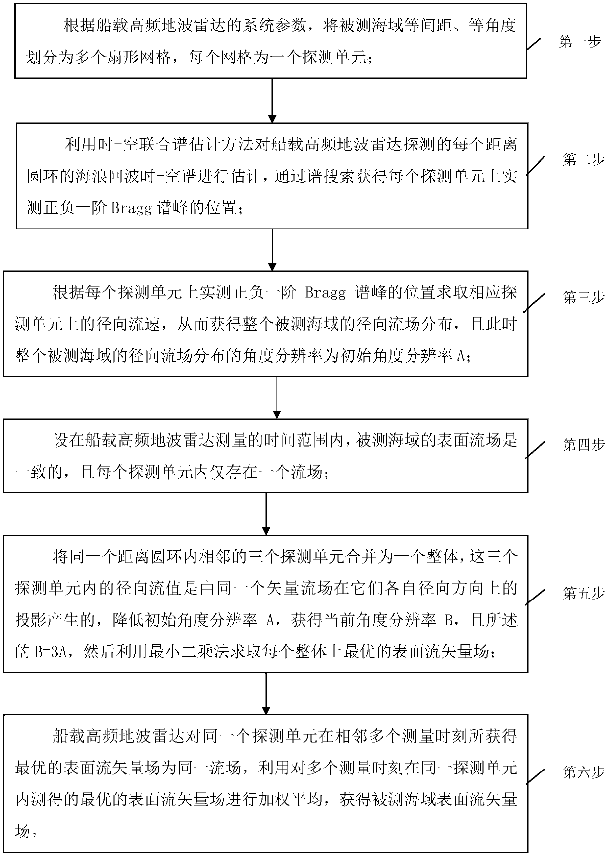
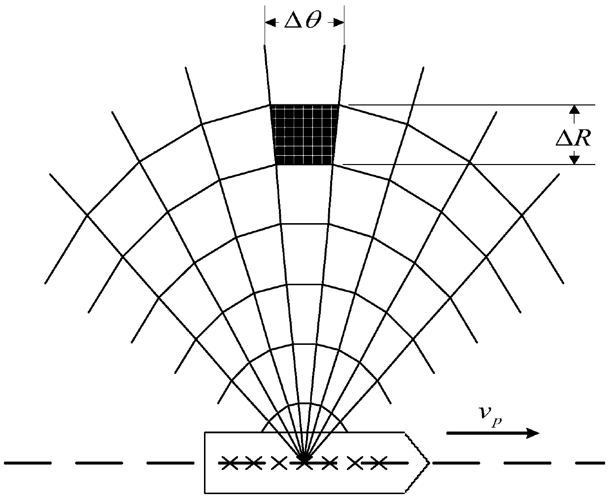
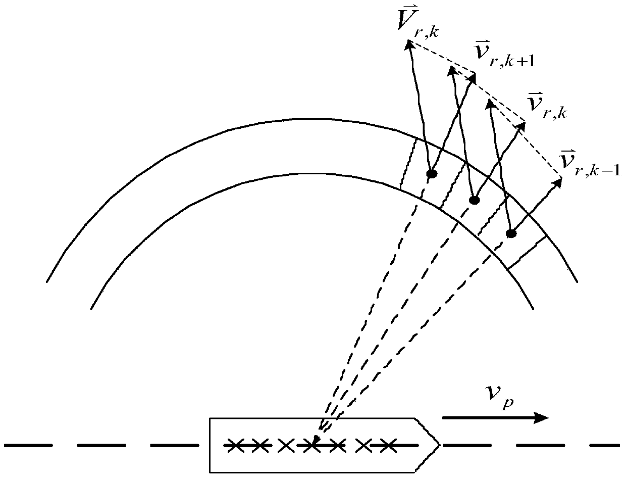
[0022] Specific implementation mode one: see figure 1 , 2 and 3 illustrate the present embodiment, a kind of surface flow measurement method based on single-station shipborne high-frequency ground wave radar described in the present embodiment, it comprises the following steps:

[0023] The first step is to divide the measured sea area into multiple fan-shaped grids with equal intervals and equal angles according to the system parameters of the ship-borne high-frequency ground wave radar, and each grid is a detection unit;

[0024] The second step is to use the time-space joint spectrum estimation method to estimate the time-space spectrum of the wave echo of each range ring detected by the ship-borne high-frequency ground wave radar, and obtain the measured positive and negative values ​​on each detection unit through spectrum search. The position of the first-order Bragg spectrum peak;

[0025] The third step is to obtain the radial flow velocity on the corresponding detec...

specific Embodiment approach 2

[0030] Specific implementation mode two: see figure 1 , 2 and 3 illustrate this embodiment. The difference between this embodiment and the surface flow measurement method based on a single-station ship-borne high-frequency ground wave radar described in the first embodiment is that in the first step described, according to the ship-borne height The system parameters of the frequency surface wave radar, the specific process of dividing the measured sea area into multiple fan-shaped grids with equal intervals and equal angles is as follows:

[0031] Firstly, the measured sea area is divided into equal intervals according to the system distance resolution of the ship-borne high-frequency ground wave radar, and then the measured sea area is divided into equal angles by using the angular resolution obtained by the azimuth estimation algorithm at this time, so as to obtain the measured sea area All sector grids of .

specific Embodiment approach 3

[0032] Specific implementation mode three: see figure 1 , 2 and 3 illustrate this embodiment, the difference between this embodiment and the surface flow measurement method based on a single-station shipborne high-frequency ground wave radar described in the second embodiment is that in the second step, the time-space The joint spectrum estimation method estimates the space-time spectrum of the wave echo of each distance ring detected by the ship-borne high-frequency ground wave radar, and obtains the position of the positive and negative first-order Bragg spectrum peaks measured on each detection unit through spectrum search. The specific process is,

[0033] The second step, the wave echo covariance matrix R of each distance ring detected by the shipborne high-frequency ground wave radar oc Perform feature decomposition to get

[0034] R oc = Σ ...


PUM


Abstract

The invention provides a surface flow measurement method based on a monostation shipborne high-frequency ground wave radar, belonging to the space-time processing field of shipborne high-frequency ground wave over-the-horizon radar signals and the ocean surface flow remote sensing field. The surface flow measurement method solves the problems of difficult synchronizing detection, small remote sensing field, high measurement cost and low observation efficiency of the traditional shore-based high-frequency ground wave radar which measures the surface flow vector field by using a two-station measurement scheme. A sea area to be measured is divided into a plurality of sector grids, and each grid is a detection unit; the position of actually measured positive / negative first-order Bragg spectral peak on each detection unit is obtained by a time-space joint spectrum estimation method and through spectrum search, and a radial flow velocity on the corresponding detection unit is obtained so that the radial flow field distribution of the measured sea area can be obtained; the optimal surface flow vector field on each unit is obtained by the least square method; the optimal surface flow vector fields which are measured in the same detection unit at a plurality of measurement moments are weighted and averaged so that the surface flow vector field of the measured sea area can be obtained. The surface flow measurement method based on the monostation shipborne high-frequency ground wave radar is specifically used for measuring the ocean surface flow.

Description

technical field [0001] The invention belongs to the field of space-time processing of ship-borne high-frequency ground wave over-the-horizon radar signals and the field of ocean surface flow remote sensing. Background technique [0002] High-frequency ground wave (surface wave) radar utilizes vertically polarized high-frequency electromagnetic waves to propagate on the surface of seawater, which has the characteristics of small propagation attenuation and good diffraction characteristics, and can provide good detection means for over-the-horizon target detection and ocean dynamic process telemetry . Compared with traditional marine monitoring methods, high-frequency ground wave radar has the advantages of long operating distance, wide coverage, high detection accuracy, good real-time performance, and all-weather service. It has broad application prospects in scientific research and other aspects. [0003] Theoretically, the positive and negative first-order Bragg peaks of ...

Claims


Application Information

Patent Timeline
Patent Type & Authority Applications(China)
IPC IPC(8): G01P5/00G01P5/18G01S13/88
Inventor 谢俊好王中宝冀振元李扬
Owner HARBIN INST OF TECH
Learn More