
Compensation devices in magnetic induction type wireless electric energy transmission equipment, and compensation methods thereof

A wireless energy transmission and magnetic induction technology, applied in reactive power compensation, circuit devices, electrical components, etc., can solve problems such as inconsistent resonance frequency, system transmission power drop, and low transmission efficiency, and achieve stable performance, easy promotion, The effect of increasing transmission power

Active Publication Date: 2014-02-26
成都艾特能电气科技有限责任公司
View PDF6 Cites 15 Cited by
  • Summary
  • Abstract
  • Description
  • Claims
  • Application Information

AI Technical Summary

Problems solved by technology

Due to factors such as the diversity of loads and the change of the coupling area between the sending end and the receiving end, the system parameters change, resulting in changes in the resonant frequencies of the sending end and the receiving end. less efficient

Method used


Image

  • Compensation devices in magnetic induction type wireless electric energy transmission equipment, and compensation methods thereof
  • Compensation devices in magnetic induction type wireless electric energy transmission equipment, and compensation methods thereof
  • Compensation devices in magnetic induction type wireless electric energy transmission equipment, and compensation methods thereof

Examples


Embodiment 1

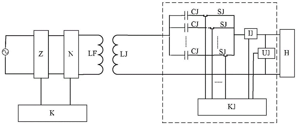
[0042] figure 1 It is shown that a specific embodiment of the present invention is a receiving compensation device in a magnetic induction wireless power transmission device, which is characterized in that:

[0043] A plurality of receiving compensation capacitors CJ are connected in parallel to form a receiving capacitor compensation array, and each receiving compensation capacitor CJ in the receiving capacitor compensation array is connected in series with the corresponding receiving electronic switch SJ; the receiving capacitor compensation array is connected in series to the magnetic induction wireless power transmission device Between the receiving coil LJ and the load H at the receiving end;

[0044] A receiving current sensor IJ is installed on the receiving coil LJ at the receiving end, and a receiving voltage sensor UJ is installed at both ends of the load H at the receiving end; each of the receiving capacitor compensation arrays receives the control terminal of the ...

Embodiment 2

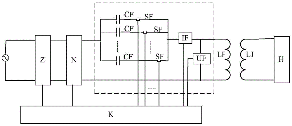
[0052] figure 2 It is shown that another specific embodiment of the present invention is a transmission compensation device in a magnetic induction wireless power transmission device, which is characterized in that:

[0053] A plurality of transmission compensation capacitors CF are connected in parallel to form a transmission capacitance compensation array, and each transmission capacitance CF in the transmission capacitance compensation array is connected in series with the corresponding transmission electronic switch SF; the transmission capacitance compensation array is connected in series in the magnetic induction wireless power transmission device Between the sending coil LF and the inverter N at the sending end;

[0054] A sending current sensor IF is installed on the sending coil LF at the sending end, and a sending voltage sensor UF is installed at both ends of the sending coil LF at the sending end; the control end of each sending electronic switch SF in the sending...


PUM


Abstract

The invention discloses compensation devices in magnetic induction type wireless electric energy transmission equipment, and compensation methods thereof. The main structure of a receiving compensation device is as follows: multiple receiving compensation capacitors are connected in parallel to form a receiving compactor compensation array, wherein the receiving compensation capacitors in the receiving capacitor compensation array are respectively connected with corresponding receiving electronic switches in series; the receiving capacitor compensation array is connected in series between a receiving coil and a load of a receiving end of the magnetic induction type wireless electric energy transmission equipment; the receiving coil of the receiving end is provided with a receiving current sensor, and the two ends of the load of the receiving end are provided with a receiving voltage sensor; and the control end of each receiving electronic switch of the receiving capacitor compensation array, the output end of the receiving current sensor and the output end of the receiving voltage sensor are connected with a receiving compensation controller. By using the devices and methods provided by the invention, the magnetic induction type wireless electric energy transmission equipment can be enabled to resonate within a rated frequency, the active power of the transmission equipment is improved, and accordingly the transmission power and transmission efficiency of the equipment are improved.

Description

technical field [0001] The invention belongs to wireless power transmission technology, in particular to a compensation device in wireless power transmission equipment and a compensation method thereof. Background technique [0002] The development of wireless energy transmission has maintained a rapid momentum, from widely used low-power (medical, consumer electronics) power transmission to high-power (electric vehicle wireless charging piles, rail transit wireless power supply systems) power transmission. Among them, the magnetic induction wireless power transmission device includes two parts: the transmitting end and the receiving end: the transmitting end converts the power frequency power into direct current through a rectifier, and then under the control of the controller, the high frequency inverter converts the direct current into high frequency alternating current. The high-frequency alternating current flows in the sending coil to generate a high-frequency magnetic...

Claims


Application Information

Patent Timeline
IPC IPC(8): H02J17/00H02J50/10
CPCY02E40/30
Inventor 麦瑞坤李勇何正友林圣
Owner 成都艾特能电气科技有限责任公司
Learn More