Novel micro-fluidic chip forming die and method

A technology of microfluidic chips and forming molds, applied in the field of micromachining, can solve the problems of long heating and cooling time of thermal conductivity materials, limitations in the wide application of polymer hot embossing technology, and the inability of polymers to completely fill the cavity. The effect of simplifying molding equipment, shortening process cycle and easy filling

A technology of microfluidic chips and forming molds, applied in the field of micromachining, can solve the problems of long heating and cooling time of thermal conductivity materials, limitations in the wide application of polymer hot embossing technology, and the inability of polymers to completely fill the cavity. The effect of simplifying molding equipment, shortening process cycle and easy filling

CN106738641APending Publication Date: 2017-05-31BEIJING UNIV OF CHEM TECH

Image

  • Novel micro-fluidic chip forming die and method
  • Novel micro-fluidic chip forming die and method
  • Novel micro-fluidic chip forming die and method

Examples


Embodiment Construction

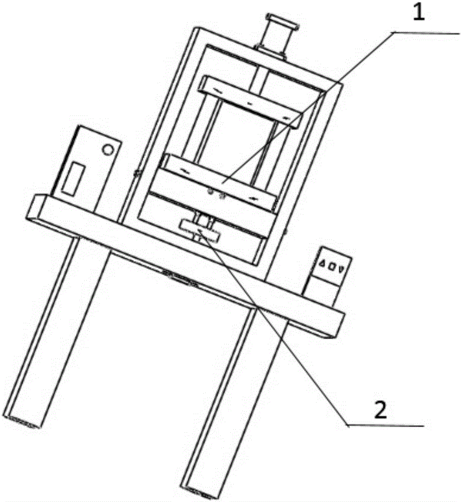
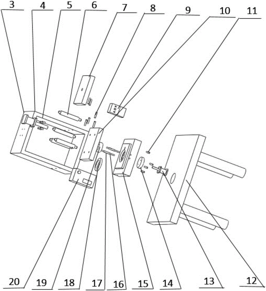
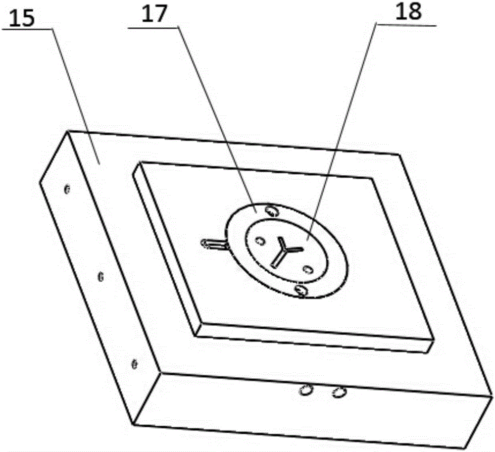
[0024] A novel microfluidic chip molding die of the present invention such as figure 1 , figure 2 , image 3 and Figure 4 As shown, the mold mainly includes: forming component 1, stripping component 2, mold clamping cylinder 3, fixing bracket 4, M5X15 hex head bolts 5 and 11, guide post 6, guide post connecting plate 7, M5X30 hex head bolt 8, Temperature controller 9, movable template 10, table 12, top mold cylinder 13, ejector pin push plate 14, mold core fixing block 15, ejector pin 16, spring sleeve 17, copper pressure block 18, mold core 19, DC power supply 20. Wherein the molding assembly 1 includes: mold core fixing block 15, mold core 19, copper pressing block 18, the mold core 19 is embedded in the lower half of the mold core fixing block 15, and the copper pressing block 18 is placed in the mold core fixing block 15 inside the mold core The upper part of the upper part of the mold core is compressed; the stripping assembly 2 includes: a top mold cylinder 13, a pu...


PUM


Abstract

The invention provides a novel micro-fluidic chip forming die and method and belongs to the field of micromachining. The die mainly comprises a forming assembly, a demoulding assembly, a die assembling air cylinder, a fixing bracket, M5*15 hexagonal head bolts, guide pillars, a guide pillar connection plate, M5*30 hexagonal head bolts, a temperature controller, a movable die plate, a table, a die jacking air cylinder, a jacking rod push plate, a core die fixing block, jacking rods, spring sleeves, a copper pressing block, a core die and a direct current power source. The novel micro-fluidic chip forming method includes the steps that die assembling is performed, wherein liquid-state dimethyl siloxane is poured into a die cavity; the direct current power source is utilized to heat the surface of the die cavity; product solidification is performed, wherein after die sinking is performed, the demoulding assembly jacks a product out; and charging bars and flanges are removed, and the product is obtained. The novel micro-fluidic chip forming method has the advantages of being energy saving, safe and high in forming precision.

Description

technical field [0001] The invention belongs to the field of micromachining, and relates to a novel hot embossing molding technology and equipment. The application fields mainly include: micron nanomachining, microelectronics, material science, optics, microelectromechanical systems, surface chemistry and other fields. Background technique [0002] In recent years, due to the application of microstructure products in more industries, the demand has increased sharply, and the precision requirements have become higher and higher. At present, most of the existing microstructure products are formed by thermal embossing of finished polymers. And the thermoplastic polymer is used, the basic principle is: firstly, the polymer substrate is heated above its glass transition temperature, and then under a certain pressure, the imprinting mold is pressed on the polymer substrate, so that the polymer is filled into the mold In the microstructure on the surface, demould after cooling and ...

Claims


Application Information

Patent Timeline
31 May 2017
Publication
CN106738641A
IPC
B29C45/26; B29C45/40; B29C45/73; B29C33/56
CPC
B29C33/56; B29C45/2602; B29C45/40; B29C45/7331
Inventors
康维嘉; 贺建芸