Apparatus and method for optically isolating a light beam from a laser

An optical isolator, laser technology, used in laser optical equipment, optics, optical components, etc., can solve problems such as increased cost, complexity and optical loss

Active Publication Date: 2014-02-26
SPI LASERS UK
View PDF4 Cites 7 Cited by
  • Summary
  • Abstract
  • Description
  • Claims
  • Application Information

AI Technical Summary

Problems solved by technology

This adds cost, compl

Method used


Image

  • Apparatus and method for optically isolating a light beam from a laser
  • Apparatus and method for optically isolating a light beam from a laser
  • Apparatus and method for optically isolating a light beam from a laser

Examples


Embodiment Construction

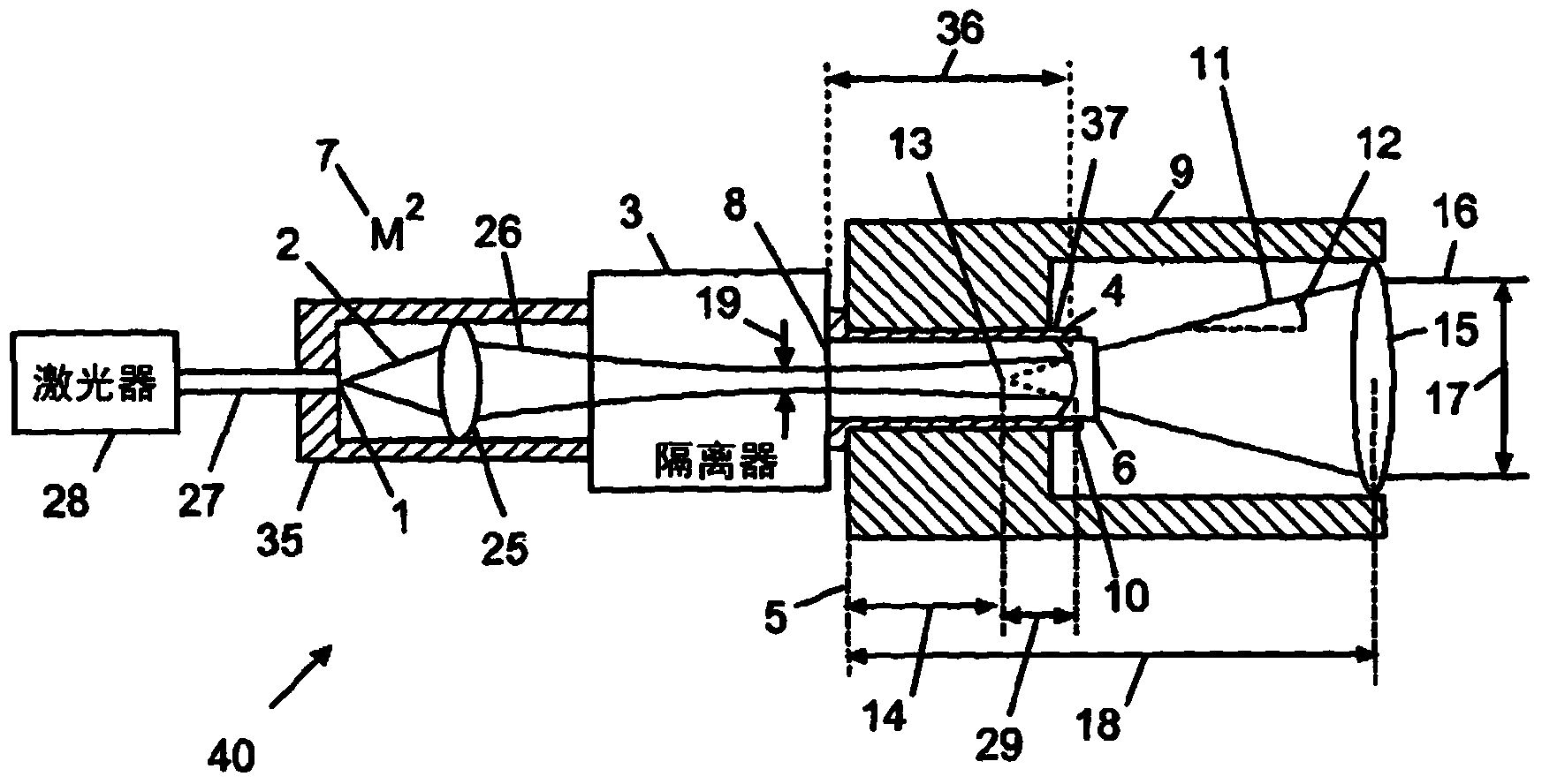
[0086] figure 1 A device for optically isolating a beam of light from a laser is shown, said device comprising an optical input 1 for a beam of light 2 , an input lens 25 , an optical isolator 3 , an output connector 4 , and a first lens structure 6 . Optical isolator 3 is selected to isolate light beam 2 having an average power greater than about 1 W, said light beam 2 being characterized by the value M 2 Defined preset beam quality7. The input lens 25 is positioned before the isolator 3, selected based on a preset beam quality 7, and focuses the beam 2 passing through the isolator 3 so that the beam diameter 19 of the beam 2 is more than one hundred within the optical isolator 3 five out of five changes. The output connector 4 is located at the output 8 of the optical isolator 3 . The output connector 4 comprises a surface forming a reference plane 5 . The first lens structure 6 is positioned to receive the light beam 2 from the isolator 3 .

[0087] The device is chara...


PUM

PropertyMeasurementUnit
Average poweraaaaaaaaaa

Abstract

Provided herein is an apparatus for optically isolating a light beam from a laser, comprising an optical isolator configured to isolate a light beam having a beam quality; a reference plane; an output connector disposed at the output of the optical isolator, wherein the output connector is configured with a common collimator interface to connect to a collimator which is capable of being mechanically referenced to the reference plane; a first lens arrangement disposed proximal to a distal end of the output connector, wherein the first lens arrangement is selected to provide an output light beam having a predetermined divergence. The laser can be selected from the group consisting of a fiber laser, a disk laser and a rod laser. Also provided herein are a system, a plurality of lasers, and a method of providing a light beam that has a consistent divergence and distance from a reference plane.

Description

technical field [0001] The present invention relates to devices and methods for optically isolating a beam of light from a laser. Background technique [0002] In the case of lasers, many applications require that the laser's output beam be optically isolated to prevent back reflections from damaging the laser or causing undesired optical interactions. Examples include welding, cutting, drilling, cladding, brazing, marking, engraving and slicing materials, especially highly reflective materials such as copper, brass, gold, silver and diamonds. Optical isolation is typically performed using an optical isolator through which the output beam of the laser is coupled. Backreflected light is then prevented back into the laser by an optical isolator. [0003] For low power laser systems, it is usually satisfactory to collimate the laser beam through an optical isolator. The beam is then expanded by a beam expander telescope and coupled into mechanical scanning optics that direct...

Claims


Application Information

Patent Timeline
IPC IPC(8): G02B6/32G02B6/42B23K26/064
CPCG02B6/4208H01S3/005G02B19/0047G02B19/0014B23K26/422B23K26/702B23K26/382B23K26/40B23K2103/08B23K2103/12B23K2103/50
Inventor M·K·邓金S·T·英格拉姆
Owner SPI LASERS UK
Why Eureka
Try Eureka