
Positioning drive mechanism for aircraft full-movement V tail

A positioning drive and aircraft technology, applied in aircraft parts, aircraft control, aircraft transmission, etc., can solve the strict requirements of assembly sequence, coordination relationship, positioning reliability and convenience of loading and unloading, reduce the transmission performance of the mechanism, and make disassembly and assembly difficult, etc. problems, to achieve the effect of improving convenience, reducing design difficulty, and good orientation

Active Publication Date: 2014-03-05
CHINA ACAD OF LAUNCH VEHICLE TECH
View PDF6 Cites 12 Cited by
  • Summary
  • Abstract
  • Description
  • Claims
  • Application Information

AI Technical Summary

Problems solved by technology

In addition, the full-motion V-tail rudder surface needs to be disassembled and assembled many times during the transportation, test, and maintenance of the aircraft, and repeated disassembly and assembly will reduce the transmission performance of the mechanism. The convenience of loading and unloading puts forward strict requirements
The positioning drive mechanism configuration of the traditional horizontal axis system and vertical axis system cannot meet the high requirements on the coaxiality of the double fulcrum of the rudder shaft of the large-aspect-ratio cantilever rudder surface due to load deformation, machining errors and assembly errors. It is difficult to disassemble and assemble in the narrow space of tooling equipment

Method used


Image

  • Positioning drive mechanism for aircraft full-movement V tail
  • Positioning drive mechanism for aircraft full-movement V tail
  • Positioning drive mechanism for aircraft full-movement V tail

Examples


Embodiment Construction

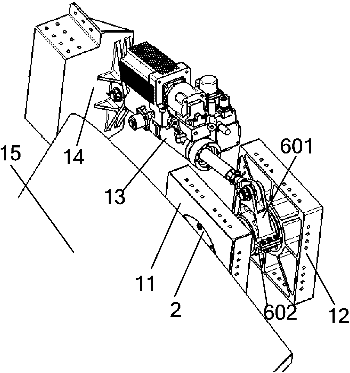
[0025] The positioning drive mechanism of the full-motion V-tail of the aircraft is connected with the fuselage structure to provide positioning and rotation support for the full-motion V-tail rudder surface, and transmit the power output from the power source to the rudder shaft to realize the swing of the rudder surface and complete the attitude control of the aircraft .

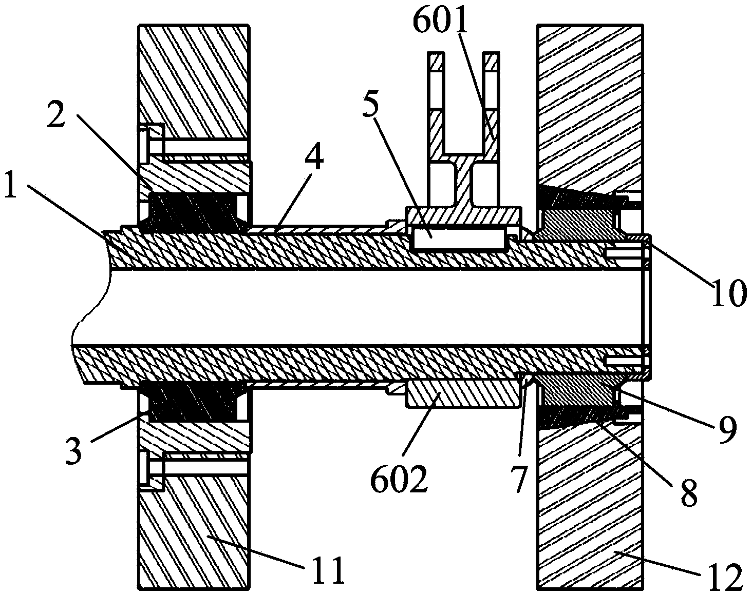
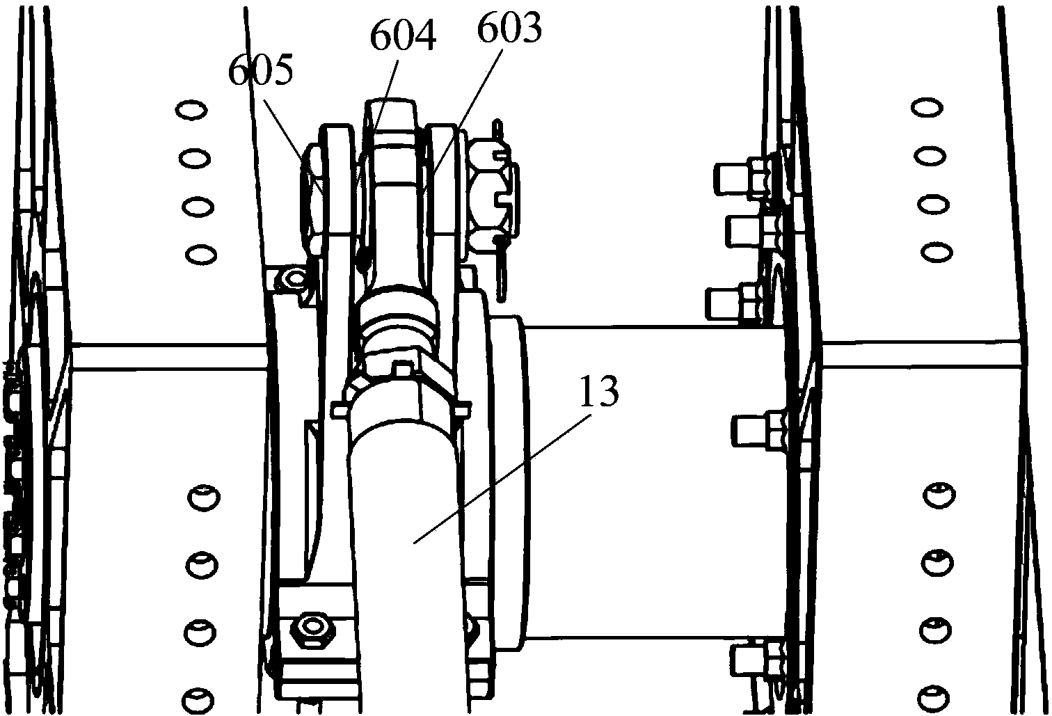
[0026] figure 1 , figure 2 They are structural schematic diagrams and cross-sectional views of the present invention, the present invention includes rudder shaft 1, upper bearing sleeve 2, upper joint bearing 3, cylindrical positioning sleeve 4, connecting key 5, split rocker arm 6, tapered positioning sleeve 7. Lower bearing sleeve 8, lower joint bearing 9, shaft end cover 10, upper bearing seat 11, lower bearing seat 12, servo actuator 13 and servo actuator support 14.

[0027] Such as figure 2 As shown, the full-motion V-tail rudder surface 15 is fixed with the rudder shaft 1. In order to adjust an...


PUM


Abstract

The invention relates to a positioning drive mechanism for an aircraft full-movement V tail. The positioning drive mechanism comprises a rudder shaft, an upper bearing sleeve, an upper joint bearing, a cylindrical positioning sleeve, a connection key, a semi rocker arm, a cone positioning sleeve, a lower bearing sleeve, a lower joint bearing, a shaft end cover, an upper bearing base, a lower bearing base, a servo actuator and a servo actuator bracket, wherein the upper bearing base and the lower bearing base are connected with an aircraft body frame to form a box-shaped structure so as to increase bending resistance and torsion resistance of the support structure, the upper joint bearing and the lower joint bearing provide rotation support for the rudder shaft, the semi rocker arm is connected with the rudder shaft through the connection key so as to change a load output by the servo actuator into a torque for driving the rudder shaft to deflect, the cone surfaces of the lower bearing sleeve and the lower bearing base are matched to perform centering, and the cylindrical surface matching position of the lower bearing sleeve and the lower bearing base is provided with threaded half holes to auxiliarily load and unload the full-movement V tail. According to the present invention, reliable positioning drive and convenient loading and unloading of the rudder surface of the aircraft with characteristics of large size, inclined angle and dual pivot point cantilever support are concurrently achieved.

Description

technical field [0001] The invention relates to a positioning driving mechanism suitable for a full-motion V-tail of an aircraft, which belongs to the field of mechanism device design. Background technique [0002] The full-motion V-tail is one of the important rudder surfaces for adjusting the attitude of the aircraft. It is symmetrically arranged on both sides of the mid-section of the aircraft and forms a certain angle with the mid-section of the fuselage. The full-motion V-tail deflects in the same direction to control the yaw and reverse deflection Control pitch. The full-motion V-tail rudder surface is large in size and weight, and is connected with the fuselage by double fulcrum support. It is a cantilever rudder surface with a large aspect ratio. The support shaft is easily deformed after bearing a large load. coaxiality. In addition, the full-motion V-tail rudder surface needs to be disassembled and assembled many times during the transportation, test, and mainten...

Claims


Application Information

Patent Timeline
IPC IPC(8): B64C9/02B64C13/24
Inventor 彭波迟令宝贾磊张庆利张涛穆星科王涛徐方舟朱永贵
Owner CHINA ACAD OF LAUNCH VEHICLE TECH
Learn More