
Crane chassis structure with bidirectional piston rod

A two-way piston and crane technology, which is applied to cranes and other directions, can solve the problems of crane load reduction, center of gravity offset, and large road damage, etc., to achieve the effect of increasing load capacity, reducing weight, and improving performance

Inactive Publication Date: 2014-03-05
宁波安涛实业有限公司
View PDF0 Cites 4 Cited by
  • Summary
  • Abstract
  • Description
  • Claims
  • Application Information

AI Technical Summary

Problems solved by technology

[0003] The crawler crane is composed of a power unit, a working mechanism, a boom, a turntable, and a chassis. Since the crane is used for hoisting heavy objects, the center of gravity is shifted due to the suspension of the heavy objects, and the weight of the cantilever of the crane. The offset of the moment caused by the shift will easily cause the crane to roll over. Therefore, the weight of the chassis must be increased to ensure the safety of the crane. However, excessive weight will cause the load of the crane's traveling mechanism and also cause the crane to damage the road surface. Larger, but also have a greater impact on the operating environment of the crane
If the weight of the chassis is reduced, the load capacity of the crane will be reduced.

Method used


Image

  • Crane chassis structure with bidirectional piston rod

Examples


Embodiment Construction

[0014] The technical solutions provided by the present invention will be described in detail below in conjunction with specific examples. It should be understood that the following specific embodiments are only used to illustrate the present invention and are not intended to limit the scope of the present invention.

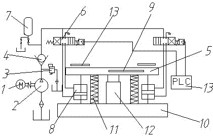
[0015] like figure 1 The crane chassis structure of a bidirectional piston rod includes a chassis 10 and a turntable structure 5, the turntable 5 is arranged on the chassis 10, and the chassis 10 and the turntable 5 are supported by The mechanism and the shock absorbing mechanism 11 are connected. The support mechanism includes a main support mechanism 12 and an auxiliary support mechanism. The main support mechanism 12 is arranged in the middle of the chassis 10. The auxiliary support mechanism includes at least Two hydraulic cylinder systems respectively arranged at the edge of the chassis, the hydraulic cylinder system includes a two-way piston rod hydraulic c...


PUM


Abstract

The invention discloses a crane chassis structure with a bidirectional piston rod. The crane chassis structure comprises a chassis and a turntable structure, wherein a turntable is arranged on the chassis; the chassis and the turntable are supported by a supporting mechanism which comprises a main supporting mechanism and an auxiliary supporting mechanism; the main supporting mechanism is arranged at the central position of the chassis; the auxiliary supporting mechanism comprises two hydraulic oil cylinder systems which are respectively arranged on the edges of the chassis; each hydraulic oil cylinder system comprises a hydraulic cylinder with the bidirectional piston rod; the upper end and the lower end of the hydraulic cylinder with the bidirectional piston rod are connected with the turntable and the chassis by adopting lifting lugs with bearings. According to the main supporting mechanism and the auxiliary supporting mechanism, part of a gap between the chassis and the turntable is adjusted by the hydraulic cylinders of the auxiliary supporting mechanism, so that the turntable is maintained on one horizontal surface all the time; the side turning of a crane due to the center-of-gravity shift caused by the suspension of a heavy object, the weight of the suspension arm and the like of the crane, and the torque shift caused by the center-of-gravity shift of the heavy object is prevented; the performance of the crawler crane is improved.

Description

technical field [0001] The invention relates to an engineering machine, in particular to a crane chassis structure with bidirectional piston rods. Background technique [0002] Crawler crane is a kind of self-propelled crane used in high-rise building construction, and it is a kind of boom rotating crane that uses crawler walking. The track has a large grounding area, good passability, strong adaptability, and can walk with a load, which is suitable for hoisting operations on construction sites. It can be used for digging, ramming, piling and other operations. [0003] The crawler crane is composed of a power unit, a working mechanism, a boom, a turntable, and a chassis. Since the crane is used for hoisting heavy objects, the center of gravity is shifted due to the suspension of the heavy objects, and the weight of the cantilever of the crane. The offset of the moment caused by the shift will easily cause the crane to roll over. Therefore, the weight of the chassis mus...

Claims


Application Information

Patent Timeline
Patent Type & Authority Applications(China)
IPC IPC(8): B66C23/62
Inventor 盛雷军王有路任适标穆素波
Owner 宁波安涛实业有限公司
Learn More