
Exhaust pollutant measuring system for in-use vehicle

A technology for measuring systems and pollutants, applied in the direction of analytical materials, instruments, etc., can solve the problems of not measuring nitrogen oxides and nitrogen dioxide, and achieve the effect of cost reduction

Inactive Publication Date: 2014-03-05
TIANJIN CPOWER TECH DEV CO LTD
View PDF6 Cites 10 Cited by
  • Summary
  • Abstract
  • Description
  • Claims
  • Application Information

AI Technical Summary

Problems solved by technology

The system uses a subsonic Venturi flowmeter (SAO) to accurately measure the flow of diluted exhaust gas, which can well solve the measurement problem of specific mass and total mass of exhaust emissions from vehicles in use; The choice of the solution solves the problem of not measuring nitrogen oxides (NO+NO 2 ), or can only measure nitric oxide (NO) but not nitrogen dioxide (NO 2 ), the optimal design of the system and the procurement and manufacturing system, as well as the self-developed CLD nitrogen oxide analyzer, reduce the cost of the measurement device and can be accepted by customers

Method used


Image

  • Exhaust pollutant measuring system for in-use vehicle
  • Exhaust pollutant measuring system for in-use vehicle
  • Exhaust pollutant measuring system for in-use vehicle

Examples


Embodiment Construction

[0023] The specific implementation manner of the present invention will be further described in detail below in conjunction with the accompanying drawings and examples.

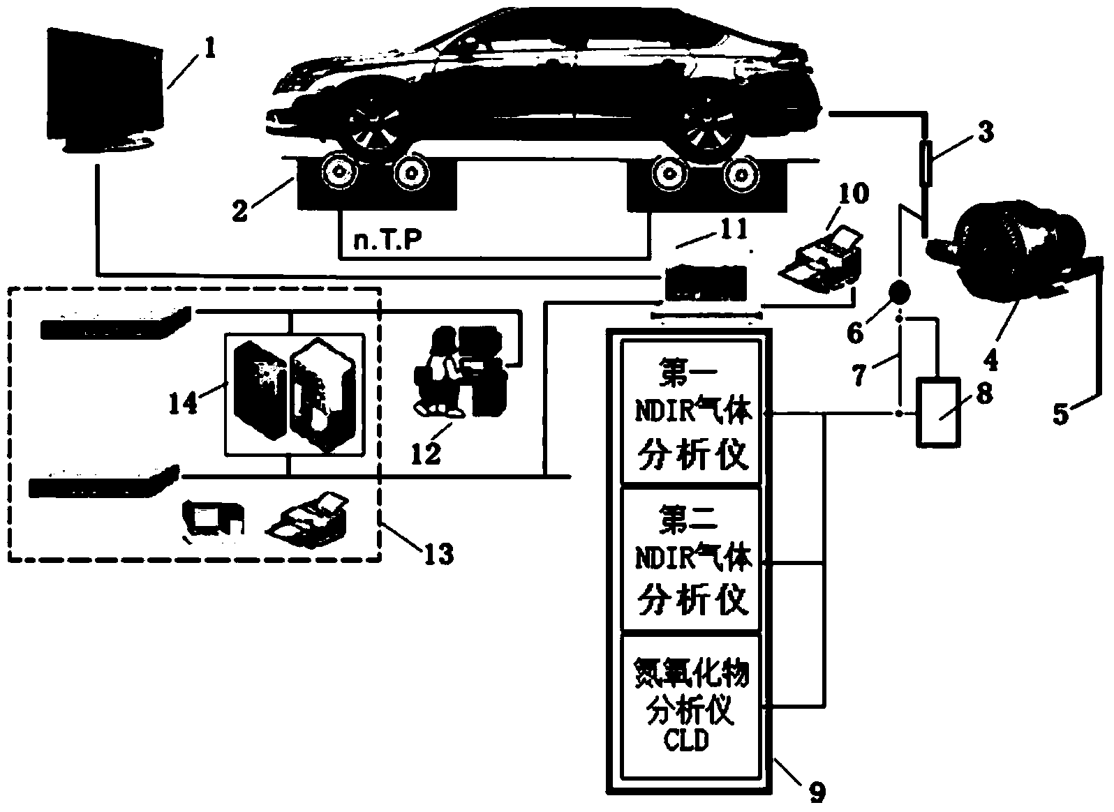
[0024] Such as figure 2 , which is a schematic diagram of the system structure of the in-use vehicle exhaust pollutant measurement system of the present invention. In the actual use environment, in addition to the exhaust pollutant measurement device, the computer control and management unit, the system also includes a chassis dynamometer device ( It is used to simulate the use state of the in-use vehicle, and provide power data during the emission measurement of the in-use vehicle, etc.). Through expansion, this system can form a multi-station detection line, and form an in-use vehicle emission measurement and management system through the local area network 13, and manage, count and analyze in-use vehicle emission measurement data from a macro perspective.

[0025] The chassis dynamometer device mainly in...


PUM


Abstract

The invention discloses an exhaust pollutant measuring system for an in-use vehicle. The exhaust pollutant measuring system comprises a diluted-exhaust-gas flow measuring and sampling unit, an exhaust-gas-component measuring and analysing unit, and the like. Diluted exhaust gas, which is exhausted by the in-use vehicle and is mixed with air, is suctioned by a cyclone draught fan (4), measured by an SAO flowmeter (3) to obtain the diluted-exhaust-gas flow and then is exhausted to the air from a draught fan exit (5). The diluted exhaust is sampled by a sampling pump (6) and enters into the exhaust-gas-component measuring and analysing unit (9) through a continuous sampling pipeline (7) or a sampling bag (8). The exhaust-gas-component measuring and analysing unit (9) comprises an NDIR analyzer for measuring CO, CO2 and O2, an NDIR analyzer for measuring HC, and a CLD analyzer for measuring NO[x] (containing NO and NO2). Compared with measuring methods and devices at present for the in-use vehicle, the exhaust pollutant measuring system provided by the invention overcomes the disadvantages of the low measuring precision of exhaust gas components, incapability of measuring both the NO and the NO2 or capability of only measuring the NO, incapability of measuring the exhausting quantity or low measuring precision, and the like. The exhaust pollutant measuring system is compatible with a plurality of measuring methods of the in-use vehicle. The price of the measuring system is medium. The measuring system is a design acceptable by the market.

Description

technical field [0001] The invention relates to a pollution detection technology of the tail gas emission of an in-use motor vehicle, in particular to a component measurement system of the tail gas emission pollutants of a motor vehicle using an ignition engine in the state of use. Background technique [0002] Statistics show that as of the end of 2012, the number of motor vehicles in the country reached 240 million, and the number of motor vehicle drivers reached 260 million, including 120 million cars, and the data is still being refreshed. In 2013, sales of cars and motorcycles are estimated to exceed 20 million units each. The driving of a large number of motor vehicles has brought increasingly deteriorating impacts on road traffic, vehicle storage, energy consumption, and environmental emissions. The situation is grim and the treatment is difficult. The whole country, especially the competent authorities, are seeking a scientific and applicable test plan that can be i...

Claims


Application Information

Patent Timeline
Patent Type & Authority Applications(China)
IPC IPC(8): G01N35/00
Inventor 李德宽李斌
Owner TIANJIN CPOWER TECH DEV CO LTD
Learn More