Radiation emission test system and radiation emission test method

A radiation emission and test system technology, applied in the field of radiation emission test systems, can solve the problems of insufficient accuracy of results, uneven quality of radiation emission test systems, failure to take into account factors affecting uncertainty, etc.

Active Publication Date: 2014-03-05
STATE GRID CORP OF CHINA +1
View PDF4 Cites 23 Cited by
  • Summary
  • Abstract
  • Description
  • Claims
  • Application Information

AI Technical Summary

Problems solved by technology

[0010] At present, the radiation emission test system built for the electromagnetic compatibility test of smart substation equipment is uneven, and the influence factors of the radiation emission test system itself on the uncertainty of the electromagnetic compatibility test are not considered, and the accuracy of the final test results is also low. not high enough

Method used


Image

  • Radiation emission test system and radiation emission test method
  • Radiation emission test system and radiation emission test method
  • Radiation emission test system and radiation emission test method

Examples


Embodiment Construction

[0031] The following will clearly and completely describe the technical solutions in the embodiments of the present invention with reference to the accompanying drawings in the embodiments of the present invention. Obviously, the described embodiments are only some, not all, embodiments of the present invention. Based on the embodiments of the present invention, all other embodiments obtained by persons of ordinary skill in the art without making creative efforts belong to the protection scope of the present invention.

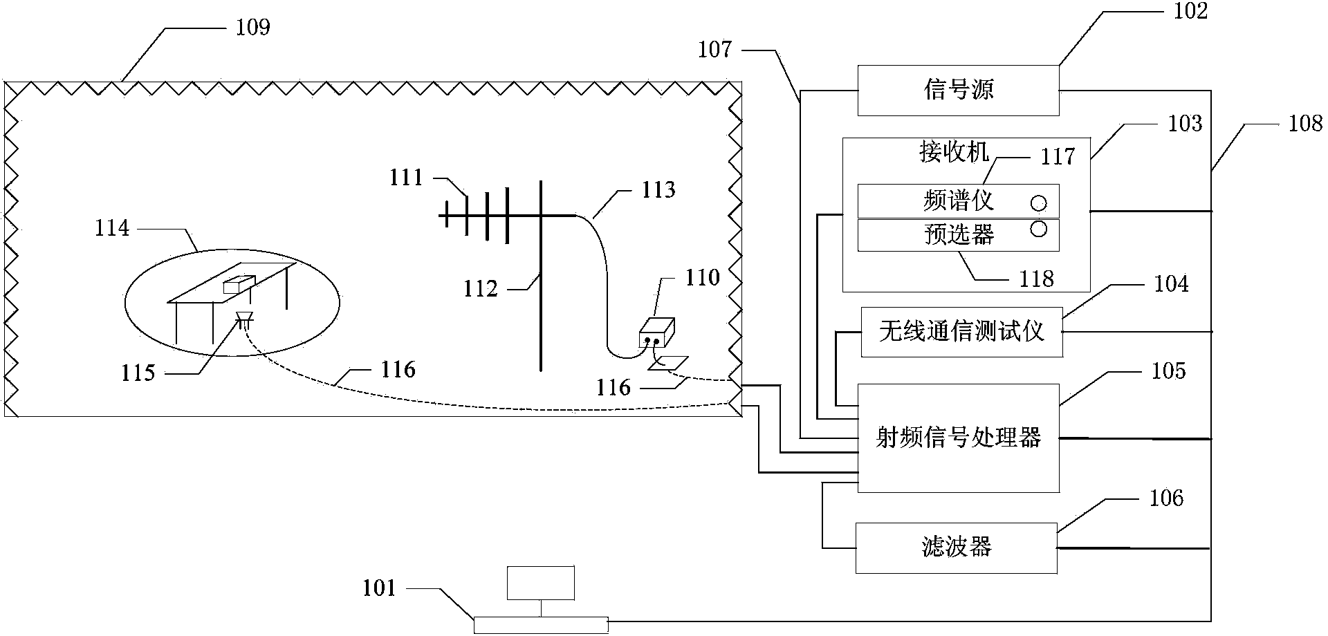
[0032] The present invention provides a radiation emission test system, such as figure 1 As shown, the system includes: control device 101, signal source 102, receiver 103, wireless communication tester 104, radio frequency signal processor 105, filter 106, radio frequency cable 107, GPIB cable 108, anechoic chamber 109, preamplifier 110, measuring antenna 111, antenna tower 112, antenna cable 113, test turntable 114, wireless communication tester antenna 115,...


PUM


Abstract

The invention provides a radiation emission test system and a radiation emission test method, and relates to the technical field of electromagnetic compatibility test. The radiation emission test system includes a control device, a signal source, a receiver, a radio communication tester, a radiofrequency signal processor, a filter, a radiofrequency cable, a general purpose interface bus (GIPB) cable, an electric wave darkroom, a preamplifier, a measuring antenna, an antenna tower, an antenna cable, a test rotary table, a radio communication tester antenna and a pre-embedded cable. The preamplifier, the measuring antenna, the antenna tower, the test rotary table and the radio communication tester antenna are arranged in the electric wave darkroom; and the pre-embedded cable is embedded in the wall of the electric wave darkroom or under the ground. By establishing a mathematical model of the electric field intensity for the radiation emission test system and analyzing various uncertain source components of the radiation emission test system, the expanded uncertainty of the radiation emission test system can be determined so that a test result can be revised, and the accuracy and the reliability of a final test result can be raised.

Description

technical field [0001] The present invention relates to the technical field of electromagnetic compatibility testing, in particular to a radiation emission testing system and method. Background technique [0002] In the power field, it is usually necessary to conduct electromagnetic compatibility tests on smart substation equipment to determine whether the smart substation equipment can operate normally in a complex electromagnetic environment. [0003] At present, the electromagnetic compatibility test for smart substation equipment must build a radiation test system in accordance with the corresponding national standards. The specific technical content involved is as follows: [0004] 1. When the device under test is a non-wireless communication device, the radiation emission test system needs to be designed according to the standard GB9254-2008, and when the device under test is a wireless communication device, the radiation emission test system needs to be designed accor...

Claims


Application Information

Patent Timeline
Patent Type & Authority Applications(China)
IPC IPC(8): G01R31/00
Inventor 李顺昕
Owner STATE GRID CORP OF CHINA
Why Eureka
Try Eureka