
Traction substation feeder cable partial discharge monitoring device and monitoring method

A technology for partial discharge monitoring and traction substations, applied in the direction of testing dielectric strength, etc., can solve the problems of unreliable determination of partial discharge of feeder cables, high price of fiber grating monitoring equipment, partial discharge faults of feeder cables, etc. The effect of timely maintenance, reduction of structure, and removal of monitoring blind spots

Inactive Publication Date: 2014-03-05
CHINA RAILWAYS CORPORATION +1
View PDF6 Cites 10 Cited by
  • Summary
  • Abstract
  • Description
  • Claims
  • Application Information

AI Technical Summary

Problems solved by technology

However, there is no special on-line monitoring device for partial discharge of feeder cables at present. Instead, the on-line temperature monitoring of feeder cables is carried out based on fiber bragg grating sensing technology. confirm
Its existing problems: 1. The price of fiber grating monitoring equipment is too high. The sensor and fiber demodulation equipment are connected by optical fiber cables. The fiber optic lines are fragile and the monitoring cost is high. Usually, they are only installed at joints and corners, which is easy to form monitoring blind spots; 2. Only the temperature of the cable is monitored. In addition to partial discharge, the reason for abnormal temperature monitoring may also be the change of external temperature or the failure of the grating temperature device itself, so it is impossible to reliably determine whether partial discharge has occurred in the feeder cable

Method used


Image

  • Traction substation feeder cable partial discharge monitoring device and monitoring method
  • Traction substation feeder cable partial discharge monitoring device and monitoring method

Examples


Embodiment

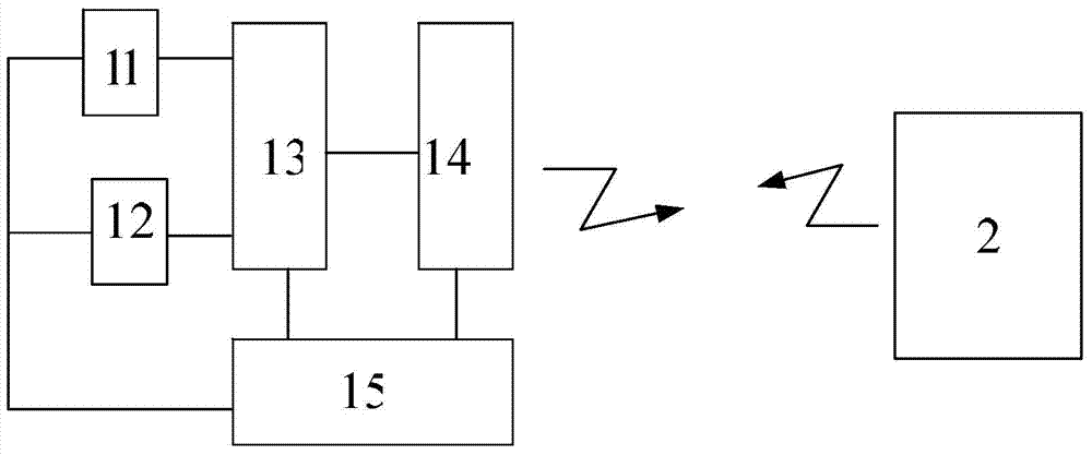
[0023] Figure 1-2 As shown, a specific embodiment of the present invention is a partial discharge monitoring device for traction substation feeder cables, which consists of:

[0024] A terminal computer 2 with a GSM signal receiving module is installed in the railway traction substation; multiple cable partial discharge monitors are distributed on the feeder cables of the traction substation; wherein, each cable partial discharge monitor 1 is composed of a sound sensor 11, a temperature sensor 12. Single-chip microcomputer 13 and GSM signal transmitting module 14 are connected successively to form and four share a power supply 15; described power supply 15 is formed by connecting successively with induction coil 15A, rectifier circuit 15B, direct-to-direct conversion circuit 15C and storage battery 15D.

[0025] The method of using the partial discharge monitoring device of this example to monitor the partial discharge of the feeder cable of the traction substation is as foll...


PUM


Abstract

The invention discloses a traction substation feeder cable partial discharge monitoring device and monitoring method. The traction substation feeder cable partial discharge monitoring device is formed in the mode that a terminal computer (2) provided with a GSM signal receiving module is installed in a traction substation; multiple cable partial discharge monitors (1) are distributed on a traction substation feeder cable; each cable partial discharge monitor (1) is composed of a sound sensor (11), a temperature sensor (12), a single-chip microcomputer (13) and a GSM signal emission module (14) in a sequential connection mode, and the sound sensor (11), the temperature sensor (12), the single-chip microcomputer (13) and the GSM signal emission module (14) share the same power supply (15); the power supply (15) is composed of an induction coil (15A), a rectifying circuit (15B), a DC / DC converting circuit (15C) and a storage battery (15D) in a sequential connection mode. The traction substation feeder cable partial discharge monitoring device is low in cost, and capable of judging and positioning a partial discharge fault point of the feeder cable comprehensively, quickly and accurately, thereby facilitating maintenance in time and better guaranteeing safe, reliable and efficient operation of the feeder cable.

Description

technical field [0001] The invention relates to a partial discharge monitoring device and a monitoring method for a feeder cable of a traction substation. Background technique [0002] At present, my country's high-speed railways are developing rapidly, and high-speed railways usually use overhead bare wires to transmit electric energy. However, in order to ensure safety and improve the reliability of power supply, high-voltage single-core cross-linked polyethylene (XLPE) cables are often used to replace overhead bare wires between the traction station and the catenary, which are called feeder cables; If there are buildings or urban areas between the grids, feeder cables must be used for power supply. If the feeder cable fails, the entire traction arm will lose power, so the feeder cable plays an important role in the traction power supply system. However, after the feeder cable is put into operation, due to its own and external factors, the insulating layer will gradually...

Claims


Application Information

Patent Timeline
Patent Type & Authority Applications(China)
IPC IPC(8): G01R31/12
Inventor 林圣程杰何正友
Owner CHINA RAILWAYS CORPORATION
Learn More