Magnetic field sensor sensitivity tuning method based on fiber bragg grating laser

A magnetic field sensor, fiber grating technology, applied in the size/direction of the magnetic field, magnetic field measurement using magneto-optical equipment, etc., can solve the problems of difficult to apply point measurement occasions, the sensor is not flexible enough, etc., to improve sensitivity and wide adaptability Effect

Inactive Publication Date: 2014-03-05
JINAN UNIVERSITY
View PDF13 Cites 4 Cited by
  • Summary
  • Abstract
  • Description
  • Claims
  • Application Information

AI Technical Summary

Problems solved by technology

[0005] The purpose of the present invention is to provide a method for tuning the sensitivity of a magnetic field sensor based on the Faraday effect and a fiber grating laser, to solve the technical problem that the sensor in the prior art is not flexible enough and difficult to apply to point measurement occasions

Method used


Image

  • Magnetic field sensor sensitivity tuning method based on fiber bragg grating laser
  • Magnetic field sensor sensitivity tuning method based on fiber bragg grating laser
  • Magnetic field sensor sensitivity tuning method based on fiber bragg grating laser

Examples


Embodiment 1

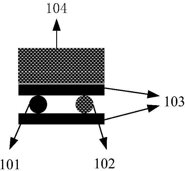
[0023] This example figure 1 As shown, the sensitivity can be tuned by temporarily changing the magnitude of the linear birefringence. In this solution, a fiber Bragg grating laser 101 and an idle fiber 102 (idle fiber 102 has the same outer diameter as the fiber Bragg grating laser) are placed in parallel and are clamped between two glass plates 103 together. The idle optical fiber 102 placed in parallel plays a supporting role and ensures that the force applied by the glass plate 103 to the fiber grating laser is perpendicular to the fiber grating laser. A weight 104 of a certain weight is placed on the glass plate above the fiber grating laser, and lateral pressure is applied to the fiber grating laser through gravity to change the shape of the fiber grating laser, thereby changing the linear birefringence in the laser cavity. By changing the weight of the weight, the linear birefringence in the laser cavity can be adjusted. In this embodiment, the linear birefringence tu...

Embodiment 2

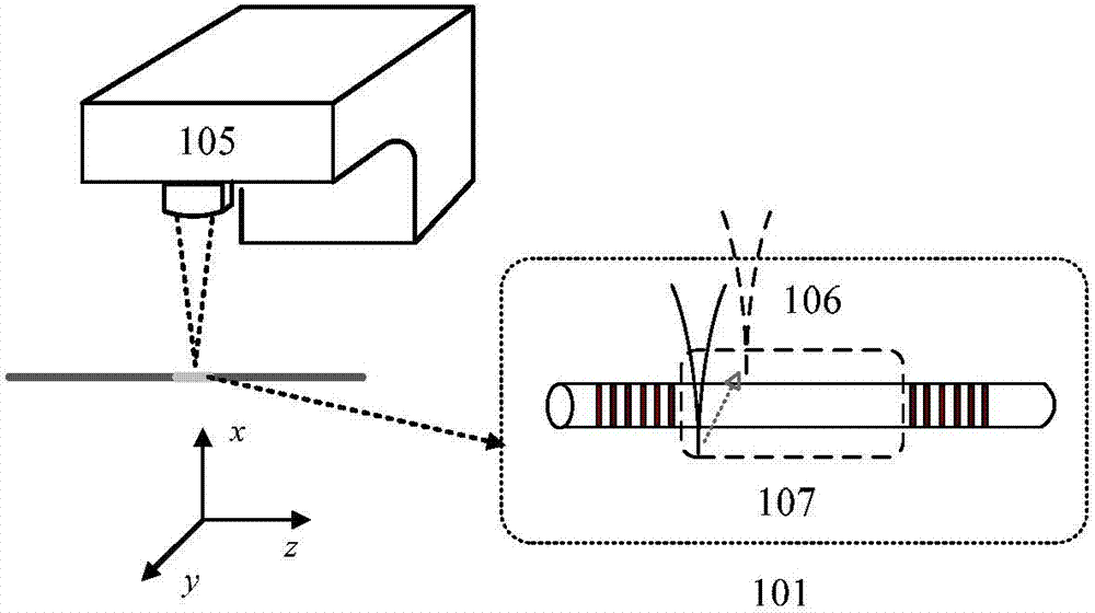
[0045] This embodiment is basically the same as Embodiment 1 in terms of realization principle; figure 2 As shown, the magnitude of the linear birefringence in the laser cavity of a fiber grating laser can be permanently changed. In this scheme, a fiber grating laser 101 is placed at the focal plane of a scanning laser beam 106 of a carbon dioxide laser 105 . The carbon dioxide laser emits a laser pulse with a repetition rate of 3 kHz, which is focused on a spot with a diameter of about 100 μm at the irradiation area 107 of the fiber grating laser through a ZnSe lens.

[0046] The beam of the CO2 laser is swept across the fiber in steps of 40 μm along the z-axis shown in the figure. Simultaneously, at each point scanned on the z-axis, the CO2 laser beam is swept across the fiber along the y-axis shown in the figure. In the process of carbon dioxide laser irradiation and scanning, the optical fiber absorbs the light with a wavelength of 10.6 μm emitted by the carbon dioxide ...


PUM


Abstract

The invention provides a magnetic field sensor sensitivity tuning method based on a fiber bragg grating laser. Linear birefringence produced in a laser cavity and circular birefringence caused by a to-be-tested magnetic field are combined to form elliptic birefringence; the fiber bragg grating laser works in a single longitudinal mode biorthogonal polarization state and produces two laser outputs; after passing through a polarizer, the two laser outputs are input into a photoelectric detector to be mixed so as to produce a beat frequency signal; by detecting frequency changes of the beat frequency signal, changes of elliptic birefringence are calculated, and the intensity of the to-be-tested magnetic field is figured out; by means of the process means of extruding optical fibers by applying lateral pressure or conducting heat treatment on the optical fibers by adopting laser lateral irradiation or the like, the magnitude of linear birefringence in the laser cavity of the fiber bragg grating laser, and magnetic field sensor sensitivity tuning can be achieved. The magnetic field sensor sensitivity tuning method has the advantages of being simple, strong in adaptability, and capable of changing sensitivity temporarily or permanently, and individually meeting actual requirements of different applications.

Description

technical field [0001] The invention relates to fiber optical measurement of magnetic field, in particular to a method for tuning the sensitivity of a magnetic field sensor based on a fiber grating laser. Background technique [0002] Fiber Bragg Grating is made by using the photosensitivity of doped fiber, and the refractive index of the fiber is permanently changed by special light irradiation. The fiber grating can reflect the incident light that satisfies the Bragg reflection condition, which is equivalent to directly writing a wavelength-selective reflector inside the optical fiber. Sensors made of fiber gratings have the advantages of small size, light weight, and high signal-to-noise ratio. However, most of these sensors use wavelength shift detection, which is complex and expensive, and the detection resolution and dynamic range are limited by the detection device. [0003] In terms of optical fiber optic measurement of magnetic field, it can be divided into direct...

Claims


Application Information

Patent Timeline
Patent Type & Authority Applications(China)
IPC IPC(8): G01R33/032
Inventor 程凌浩金龙关柏鸥韩建磊郭贞贞
Owner JINAN UNIVERSITY
Why Eureka
Try Eureka