Double-stator magnetic suspension switch reluctance starting/power generation machine

A switched reluctance and magnetic levitation technology, applied in electrical components, electromechanical devices, holding devices with magnetic attraction or thrust, etc., can solve problems such as mechanical bearing wear, and achieve compact structure, clear functions, and improved control flexibility. Effect

Inactive Publication Date: 2014-03-05
NANJING INST OF TECH
7 Cites 15 Cited by

AI-Extracted Technical Summary

Problems solved by technology

[0007] Aiming at the deficiencies in the prior art, the purpose of the present invention is to provide a dual-stator magnetic levitation switch reluctance start that decouples the main winding from the suspension winding, improves the radial suspension performance, and integrates the functions of the electric starter,...

Method used

Referring to Fig. 2 and Fig. 3, the magnetic flux paths of the main winding 3 and the suspension winding 8 of the present invention are independent of each other, which solves the strong coupling problem of the main winding 3 and the suspension winding 8 in the traditional magnetic levitation switched reluctance motor.
[0042] The main winding pole 2 of the outer stator 1 of the present invention is wound with a main winding 3 to realize start-up and power generation functions; the suspension pole 7 of the inner stator 6 is wound with a suspension winding 8 to realize the rotor 4 suspension function. The magnetic flux paths of the main winding 3 and the suspension winding 8 are independent of each other, which solves the coupling problem between the power generation function and the rotor suspension function; given the winding current of the radial force, during the rotation of t...

Abstract

The invention discloses a double-stator magnetic suspension switch reluctance starting/power generation machine which sequentially comprises an inner stator, a rotor and an outer stator from inside to outside, the inner stator, wherein the rotor and the outer stator are in the salient pole type and are nested in a concentric mode; M main winding poles are arranged on the outer stator at equal intervals, and each main winding pole is provided with a main winding which achieves starting and power generation functions; N rotor salient poles are arranged on the rotor at equal intervals; O suspension poles are arranged in the inner stator at equal intervals, and each suspension pole is provided with a suspension winding which achieves a rotor suspension function; magnetic flow paths of the main windings are independent of magnetic flow paths of the suspension windings, the coupling problem between the starting/ power generation function and the suspension function is solved, aligning areas of the suspension poles and the rotor are equal to pole widths of the suspension poles, and radial suspension performance is improved. The machine integrates the starting and power generation functions and the rotor self-suspension function, the structure of an engine can be more compact, and the engine is convenient to maintain and control.

Application Domain

Dynamo-electric machinesMagnetic holding devices

Technology Topic

Coupling problemStator +5

Image

  • Double-stator magnetic suspension switch reluctance starting/power generation machine
  • Double-stator magnetic suspension switch reluctance starting/power generation machine
  • Double-stator magnetic suspension switch reluctance starting/power generation machine

Examples

  • Experimental program(1)

Example Embodiment

[0029] In order to make the technical means, creative features, objectives and effects of the present invention easy to understand, the present invention will be further explained below in conjunction with specific embodiments.
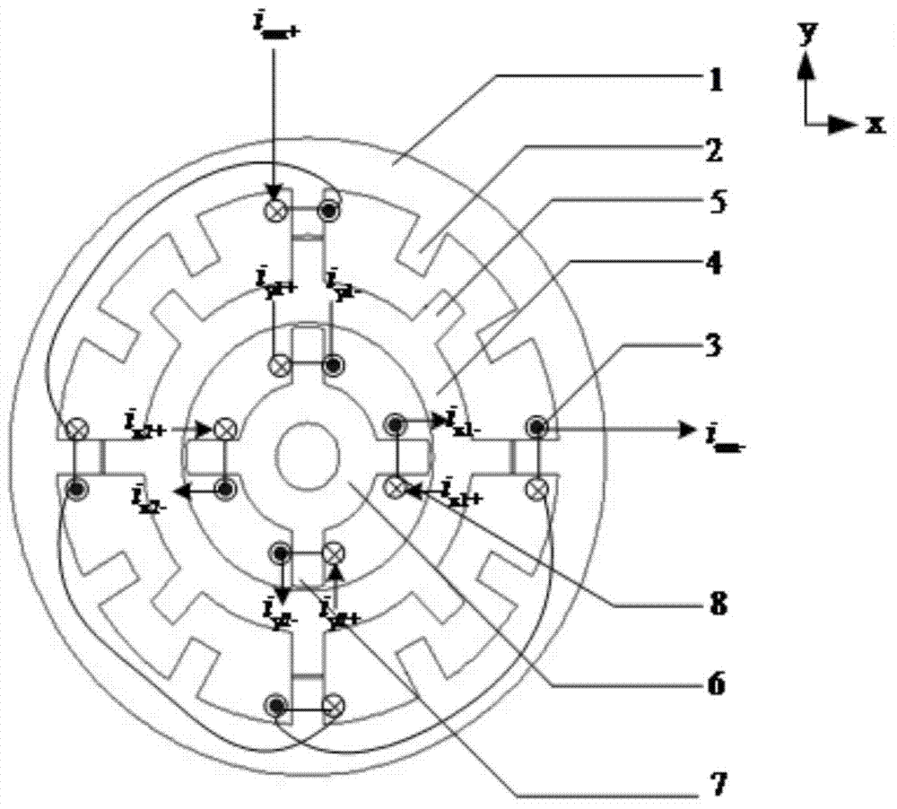
[0030] See figure 1 , The double stator magnetic levitation switched reluctance starter/generator of this embodiment includes an outer stator 1, a rotor 4 and an inner stator 6 to form a three salient pole structure, the rotor 4 and the inner and outer stators are nested in a concentric manner Together.
[0031] Twelve main winding poles 2 are arranged on the outer stator 1 at equal intervals, the pole width of the main winding pole 2 is 15°, and the main winding 3 is respectively wound, and the main windings 3 on the radially opposite vertical four poles are connected in series. Phase, divided into three phases ( figure 1 Only one phase is drawn in the middle, and the other two phases are omitted).
[0032] Eight salient rotor poles 5 are arranged on the rotor 4 at equal intervals without any windings.
[0033] The four suspension poles 7 are arranged on the inner stator 6 at equal intervals, and the suspension windings 8 are respectively wound, and the suspension windings 8 are not connected in series with each other.
[0034] The suspension winding 8 is responsible for the suspension function of the rotor 4, and the required suspension force is obtained by individually controlling the current of each suspension winding 8.
[0035] The suspension force in the x direction is determined by the current i of the suspension winding 8 x1 And i x2 Control when i x1 When it is turned on, it produces a positive suspension force in the x direction. On the contrary, when i x2 When turned on, a suspension force in the negative x direction is generated; similarly, the suspension force in the positive and negative directions can also be generated in the y direction; the suspension force in the x direction and the y direction can be combined with the suspension force in any direction, so as to realize the rotor 4 of the generator automatically Floating function, i in the figure x1+ , I y1+ And i x2+ , I y2+ Respectively, the current flowing into the floating winding 8 in the positive and negative directions of the x and y axes; i x1- , I y1- And i x2- , I y2- Respectively, the current flowing out of the suspension winding 8 in the positive and negative directions of the x and y axes. During the rotation of the rotor 4, the alignment area of ​​the suspension pole 7 and the rotor 4 is always equal to the width of the suspension pole 7, which is beneficial to generate radial force, and the radial force does not change with the position angle of the rotor 4; therefore, only a small suspension is required The current of the winding 8 can control the rotor 4 at the radial center position, which can effectively enhance the radial suspension capacity and improve the dynamic and static performance of the suspension subsystem.
[0036] The main winding 3 is responsible for starting and generating functions. The radially and vertically opposed four-pole main windings are connected in series into one phase, which is divided into three phases A, B, and C, which are controlled by a three-phase asymmetric half-bridge power circuit. Phases B and C are respectively Located at 1/3 and 2/3 of the rotation direction of phase A. I in the picture ma+ Inflow current for phase A main winding; i ma- The current flows from the A-phase main winding. It is defined that when the salient pole 5 of the rotor is aligned with the pole 2 of the main winding, it is the zero degree position of the position angle θ of the rotor 4, and the counterclockwise direction is positive. The alignment area of ​​the suspension pole 7 and the rotor 4 is always equal to the pole width of the suspension pole 7, and the magnetic linkage of the suspension winding 8 does not change with the position angle of the rotor 4, indicating that the suspension force is not affected by the position angle of the rotor 4 and is always effective during the rotation of the rotor 4 Ground produces suspension force.
[0037] When starting, the dual-winding magnetic levitation switched reluctance starter/generator operates as an electric starter. Take the A-phase main winding on the outer stator 1 as an example, the torque current i ma A four-pole symmetrical main magnetic flux will be generated. According to the principle of minimum reluctance, the rotor 4 will move in the direction aligned with the stator poles under the action of the magnetic field of the main winding 3. When the A, B, and C three-phase windings are controlled to turn on in turn When, the rotor 4 rotates clockwise, otherwise it rotates counterclockwise. When generating electricity, the dual-winding magnetic levitation switch reluctance starter/generator operates as a generator. Take the A-phase main winding on the outer stator 1 as an example. Suppose the motor is driven by an external force to rotate in a counterclockwise direction. When the rotor 4 magnetic pole axis moves to coincide with the stator C-phase winding, the stator A-phase main winding is energized, namely The switch tube is closed, and the phase is excited by the DC power supply. The salient poles of the rotor 5 will have a tendency to move toward the stator A phase, and will be subjected to a torque in the opposite direction (ie clockwise) to the driving torque of the external force. At the same time, the mechanical energy on the rotor 4 is converted into magnetic energy and stored in the magnetic field. When the switch tube is turned off, the A-phase current flows through the diode without changing the direction of the current in the winding. The magnetic energy stored in the magnetic field will be released and converted into electrical energy to be fed back to the power supply, thus completing the transfer between mechanical energy and electrical energy. The electromechanical energy conversion process with the magnetic field as the medium. In this way, the motor is continuously excited in the order of A-B-C-A, and the mechanical energy acting on the rotor 4 will be continuously converted into electrical energy to realize power generation operation. If the external force drives the torque in the opposite direction, only the excitation sequence needs to be changed to maintain its power generation state.
[0038] See figure 2 with image 3 The magnetic flux paths of the main winding 3 and the suspension winding 8 of the present invention are independent of each other, which solves the problem of strong coupling between the main winding 3 and the suspension winding 8 in the traditional magnetic levitation switched reluctance motor.
[0039] See Figure 4 During the rotation of the motor, the inductance of the main winding 3 changes with the position angle of the rotor 4. At the same time, when the current of the main winding 3 is increased, the saturation of the core will increase, so the inductance of the main winding 3 will decrease.
[0040] See Figure 5 When the radial force winding current is given, the suspension force can be basically kept constant during the rotation of the rotor 4, which eliminates the problem that the suspension force cannot be effectively generated when the stator and rotor are critically aligned in the traditional magnetic levitation switched reluctance motor. Improved radial suspension performance.
[0041] See Image 6 , The main switch of each phase main winding 3 switch circuit is at θ=θ on Is triggered at θ=θ off Turn off at the moment. I.e. θ on ≤θ≤θ off The phase is the excitation phase, which provides energy Q to the system through the outside world 1;Θ off off -θ on The stage is the feedback power generation stage, which provides energy Q to the outside in the form of pulsed electric energy 2; The actual output power of power generation is the power generation Q 2 And excitation power difference Q 1.
[0042] In the present invention, the main winding pole 2 of the outer stator 1 is wound with a main winding 3 to realize the function of starting and generating power; the suspension winding 8 is wound on the suspension pole 7 of the inner stator 6 to realize the suspension function of the rotor 4. The magnetic flux paths of the main winding 3 and the suspension winding 8 are independent of each other, which solves the coupling problem between the power generation function and the rotor suspension function; given the radial force winding current, the suspension force can be basically Keep constant, improve radial suspension performance. The generation of radial force does not require the main winding 3 to provide a bias magnetic field, and the conduction intervals of the main winding 3 and the suspension winding 8 do not restrict each other, which improves the flexibility of control method research and selection. The magnetic bearing technology is applied to the switched reluctance starter/generator. On the basis of retaining the excellent performance of the switched reluctance starter/generator, the friction loss caused by the mechanical bearing is further eliminated, and no lubrication device is required. Integrating the functions of starting, power generation and rotor self-suspension can effectively release the engine space, make the engine structure more compact, and help optimize engine performance.
[0043] The basic principles and main features and advantages of the present invention have been shown and described above. Those skilled in the industry should understand that the present invention is not limited by the foregoing embodiments. The foregoing embodiments and descriptions only illustrate the principles of the present invention. Without departing from the spirit and scope of the present invention, the present invention may have Various changes and improvements, these changes and improvements fall within the scope of the claimed invention. The scope of protection claimed by the present invention is defined by the appended claims and their equivalents.

PUM

no PUM

Description & Claims & Application Information

We can also present the details of the Description, Claims and Application information to help users get a comprehensive understanding of the technical details of the patent, such as background art, summary of invention, brief description of drawings, description of embodiments, and other original content. On the other hand, users can also determine the specific scope of protection of the technology through the list of claims; as well as understand the changes in the life cycle of the technology with the presentation of the patent timeline. Login to view more.

Similar technology patents

Fluorine-cation-containing WPU (waterborne polyurethane) and preparation method thereof

ActiveCN103044649AClear structureRaw material controllableSolventIsocyanate compound
Owner:无锡智慧兴宜信息技术有限公司

Classification and recommendation of technical efficacy words

  • Clear structure
  • Clear function

Silicon phthalocyanine compound and composite, their preparation and application thereof

ActiveCN1861603AStrong photosensitivityClear structureSilicon organic compoundsSilicon compound active ingredientsCompound sDisease
Owner:FUZHOU UNIVERSITY

Active-active method for cloud data center management platforms

InactiveCN103812929AClear structureComplete layoutTransmissionInstrumentsVirtualizationData cloud
Owner:LANGCHAO ELECTRONIC INFORMATION IND CO LTD

Freight management system, method and storage medium

InactiveCN109118133AClear functionTimely freight managementOffice automationResourcesManagement systemOrder management
Owner:因为科技无锡股份有限公司
Why Eureka
Try Eureka