Low pass filter

A low-pass filter and filter technology, applied in the direction of impedance network, electrical components, multi-terminal pair network, etc., can solve problems such as large capacitance ratio, difficult matching accuracy of capacitors, difficult tunability of filter components, etc.

Inactive Publication Date: 2014-03-05
SUZHOU BATELAB MICROELECTRONICS
View PDF4 Cites 3 Cited by
  • Summary
  • Abstract
  • Description
  • Claims
  • Application Information

AI Technical Summary

Problems solved by technology

This will lead to difficult tunability of filter components because of the flexibility of cutoff frequency, DC gain and Q factor
Second, in order to achieve a definite Q factor of Q>1, the capacitance ratio can be quite large, making it difficult to match capacitors to a good accuracy
Finally, the total capacitance required by the MFB circuit is quite high, which leads to higher manufacturing costs and a wider range of die area

Method used


Image

  • Low pass filter
  • Low pass filter
  • Low pass filter

Examples


Embodiment Construction

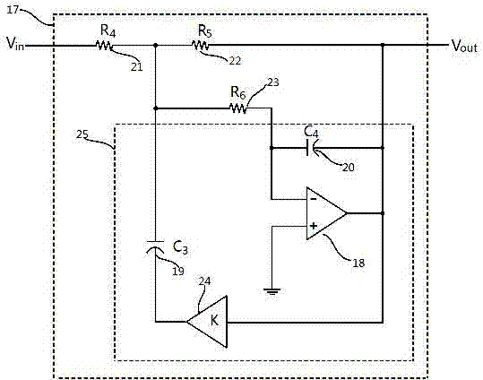
[0030] The present invention provides a fully tunable second-order low-pass filter with minimal active circuits, which can be easily cascaded to form higher-order filters. A second-order low-pass filter is best constructed from a second-order MFB low-pass filter circuit by inserting a positive feedback loop between the output of the op-amp and the capacitor previously connected to ground in the MFB configuration. The feedback loop makes the IC a fully programmable second-order low-pass filter building block, which provides a very flexible choice of filter parameters, such as cutoff frequency, DC gain, and Q factor, all by choosing appropriate resistor values.

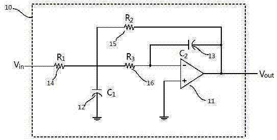
[0031] refer to figure 1 , depicts the block diagram and circuit diagram of a prior art second-order MFB low-pass filter. The filter circuit 10, which implements a second-order low-pass filter, includes: an operational amplifier 11, a capacitor C 1 (12) and C 2 (13), resistor R 1 (14), R 2 (15) and R 3 (16). ...


PUM


Abstract

Disclosed is a low pass filter. According to the filter, parameters, such as the cut-off frequency, the direct-current gain and the Q factor, of the filter can be quite flexibly selected. Due to the fact that a proper resistance value is selected for a single integrated circuit by the low pass filter, compared with configurations of low pass filters of other standards, the low pass filter has the quite low capacitance, the quite low capacitivity and an active circuit.

Description

technical field [0001] The present invention generally relates to continuous time analog integrated circuit filters. More specifically, the present invention provides a fully tunable second order low pass filter with minimal active circuitry. Background technique [0002] Analog filters are essential to the operation of most electronic circuits and are often used to separate signals from noise. In general, an analog filter is an electrical network that alters the amplitude and / or phase characteristics and attenuates signals at other frequencies relative to signals in one or more frequency bands that pass freely. [0003] Filters are divided into five basic types according to frequency band: all-pass, band-pass, notch, low-pass, and high-pass. An all-pass filter has no effect on the amplitude of the signal at different frequencies, its function is to simply change the phase of the signal without affecting the signal amplitude. The other four types of filters freely pa...

Claims


Application Information

Patent Timeline
Patent Type & Authority Applications(China)
IPC IPC(8): H03H7/01
Inventor 不公告发明人
Owner SUZHOU BATELAB MICROELECTRONICS
Why Eureka
Try Eureka