Lead frame and power module

A lead frame and lead technology, applied in electrical components, semiconductor devices, electric solid devices, etc., can solve the problems of low material yield and so on.

Inactive Publication Date: 2014-03-05
TOYOTA JIDOSHA KK
View PDF7 Cites 0 Cited by
  • Summary
  • Abstract
  • Description
  • Claims
  • Application Information

AI Technical Summary

Problems solved by technology

[0007] However, in the conventional lead frame, the outer peripheral part is cut off and discarded after forming the molding resin, so there is a problem that the yield of the material is low.

Method used


Image

  • Lead frame and power module
  • Lead frame and power module
  • Lead frame and power module

Examples


Embodiment Construction

[0026] Embodiments of a lead frame and a power module to which the present invention is applied will be described below.

[0027] First, before describing the lead frame and the power module of the embodiment, the figure 1 and figure 2 , the lead frame of the comparative example will be described.

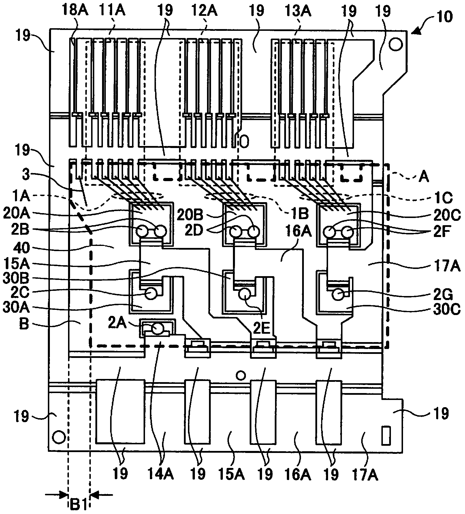
[0028] figure 1 is a diagram showing a state where IGBTs (Insulated Gate Bipolar Transistor: insulated gate bipolar transistors) 20A to 20C and diodes 30A to 30C are connected to the lead frame 10 of the comparative example. For the diodes 30A to 30C, for example, FWDs (Fly Wheel Diodes: freewheeling diodes) may be used.

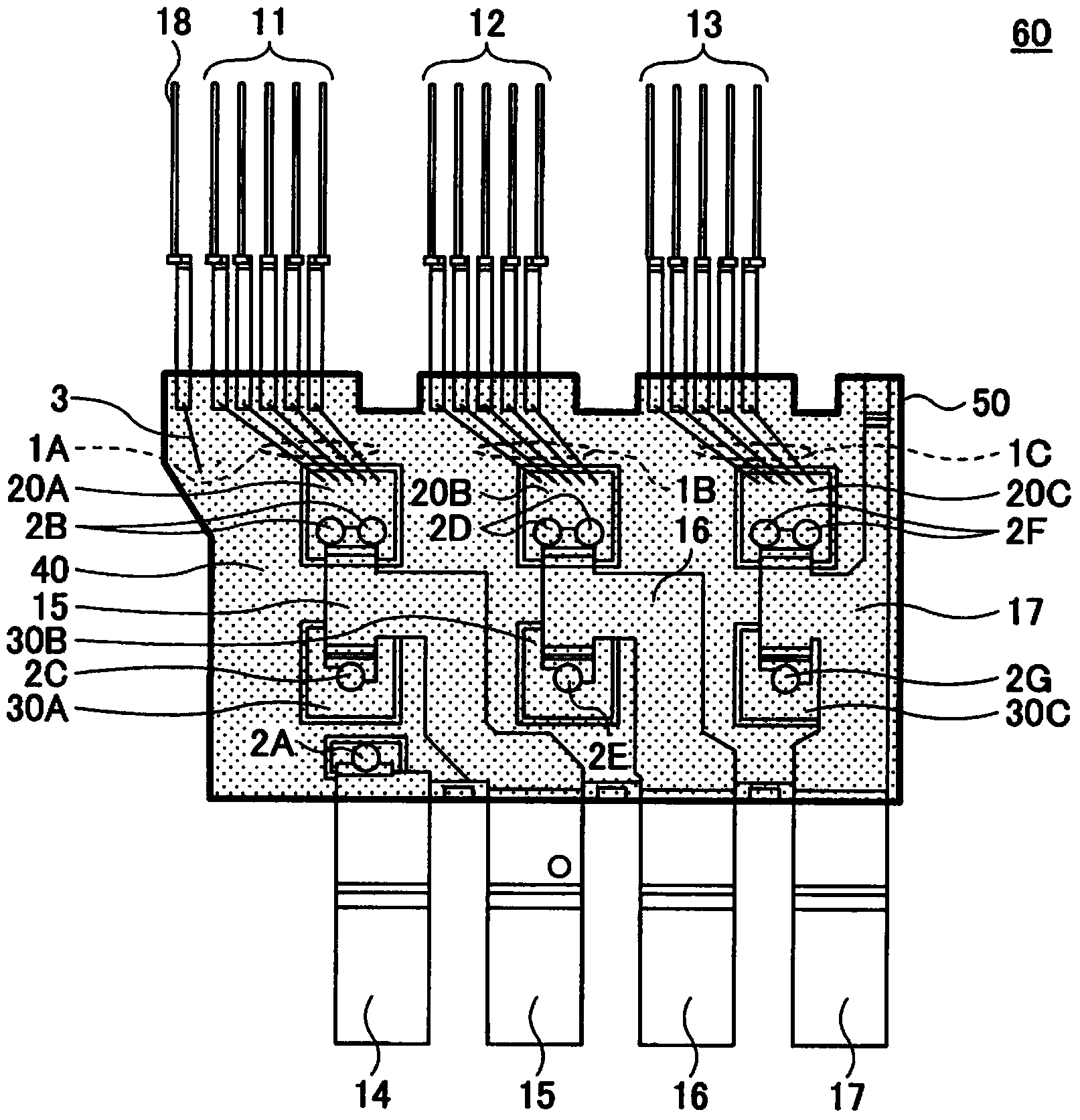
[0029] The lead frame 10 of the comparative example includes signal lead portions 11A, 12A, and 13A, power lead portions 14A, 15A, 16A, and 17A, and a voltage detection lead portion 18A. In the lead frame 10, cut off after passing through, as signal lead parts 11, 12, 13, power lead parts 14, 15, 16, 17 and voltage detection lead part 18 (refer to figure 2...


PUM


Abstract

The present invention addresses the problem of providing a lead frame and a power module with a high material yield. The lead frame includes: multiple first leads that extend on one side of a region where a semiconductor element is provided in a plan view; multiple second leads that extend on the other side opposite to the one side of the region where the semiconductor element is provided in the plan view; a third lead that is provided on the outer side of the first lead positioned at one end of the multiple first leads in the plan view; and a wiring section that is connected to the third lead, constitutes a portion of a guide frame for the first leads, second leads, and third lead, and is used as wiring to be connected to the third lead after portions of the guide frame excluding the above-mentioned portion are removed.

Description

technical field [0001] The invention relates to a lead frame and a power component. Background technique [0002] Conventionally, there has been a lead frame in which at least an island on which a semiconductor chip is mounted, leads connected to the semiconductor chip via bonding wires, and the island and the In a lead frame in which leads are connected and fixed to a tie bar on a lead frame main body, reinforcing protrusions are provided on the outer peripheral portion of the lead frame main body (for example, refer to Patent Document 1). [0003] prior art literature [0004] patent documents [0005] Patent Document 1: Japanese Patent Laid-Open No. 2008-218455 Contents of the invention [0006] The problem to be solved by the invention [0007] However, in the conventional lead frame, since the outer peripheral portion is cut off and discarded after forming the molding resin, there is a problem that the material yield is low. [0008] Therefore, the object of the ...

Claims


Application Information

Patent Timeline
Patent Type & Authority Applications(China)
IPC IPC(8): H01L23/50H01L23/48H01L25/07H01L25/18
CPCH01L25/16H01L23/49575H01L23/49541H01L2924/19107H01L2224/73221H01L23/4334H01L2924/13091H01L23/495H01L2924/15747H01L24/34H01L23/492H01L2224/48091H01L22/34H01L2224/48247H01L2224/48465H01L25/18H01L2924/13055H01L25/072H01L23/49551H01L23/49555H01L2924/1306H01L2924/1305H01L2224/40137H01L2924/181H01L2224/40095H01L24/40H01L23/49537H01L24/48H01L24/49H01L24/73H01L2224/49171H01L2224/73263H01L2224/73265H01L2924/00014H01L2224/83801H01L24/37H01L2224/37147H01L2224/84801H01L2224/371H01L24/84H01L2224/0603H01L2924/00H01L2924/00012H01L2224/45099H01L24/36H01L23/3114H01L23/4951H01L23/4952H01L23/49562H01L23/49568H01L24/85H01L2224/859
Inventor 门口卓矢三好达也川岛崇功奥村知巳
Owner TOYOTA JIDOSHA KK
Why Eureka
Try Eureka