Eureka AIR delivers breakthrough ideas for toughest innovation challenges, trusted by R&D personnel around the world.

Electrical tar precipitator

A technology of an electric tar catcher and a feeding box is applied in the field of electric tar catcher, and can solve the problems of explosion of the electric tar catcher, safety production accident, and it can only be installed outdoors.

Inactive Publication Date: 2014-03-12
乌鲁木齐德旺源鑫节能环保科技有限公司
View PDF10 Cites 9 Cited by
  • Summary
  • Abstract
  • Description
  • Claims
  • Application Information

AI Technical Summary

Problems solved by technology

The minimum height of the current electric tar catcher is about 11 meters, and it can only be installed outdoors. After use in winter, a heater is required to heat the inside of the kiln body in time. The inside of the current electric tar catcher; The hoisting frame with a straight vertical corona wire inside is composed of an upper hanger, an upper hanger, a lower hanger and a lower hanger. The lower end is fixed to the lower hanger, and each hexagonal edge tube (precipitation pole) passes through the corona wire (corona electrode) between the upper and lower hangers, and passes through each hexagonal edge tube. The lower ends are respectively connected to the upper hanger and the lower hanger. When the electric tar catcher with the lifting frame or other electric tar catchers are working, the electric tar catcher must be guarded and used in strict accordance with the operating rules, otherwise, the corona wire and There is a possibility of arcing between the hangers or between the upper and lower hangers, and the possible arc (electric spark) will ignite the gas in the electric tar catcher, and even cause the electric tar catcher to explode, causing serious safety production accidents

Method used


Image

  • Electrical tar precipitator
  • Electrical tar precipitator

Examples


Embodiment Construction

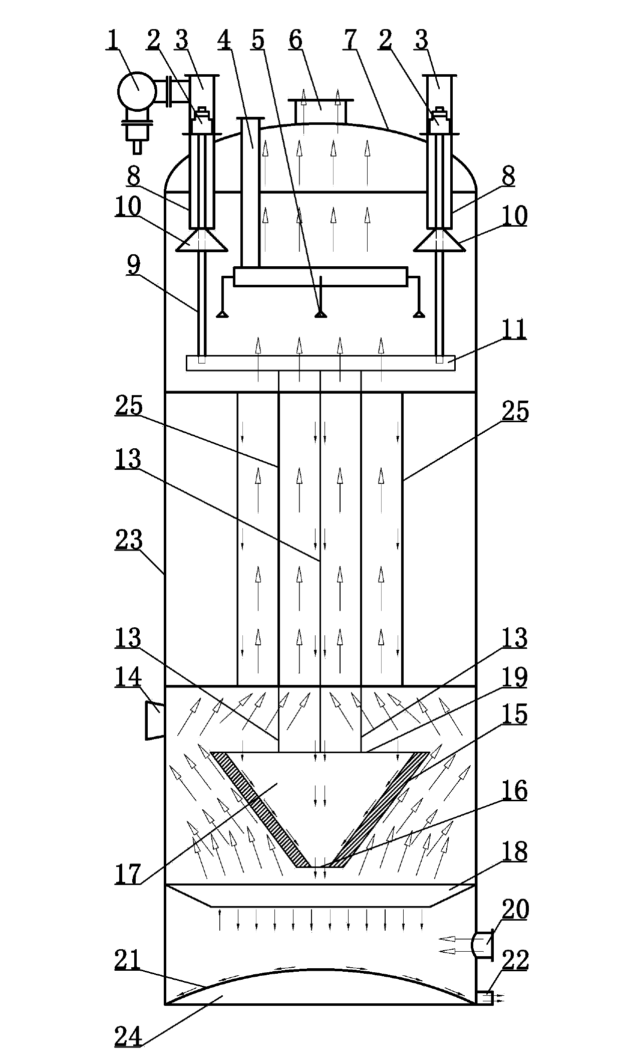
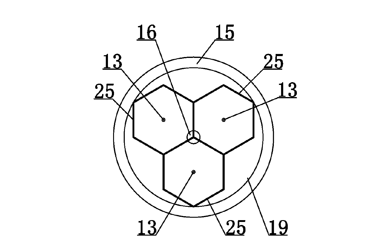
[0009] An electric tar catcher, such as figure 1 , figure 2 As shown, it includes a vertical cylinder 23, a head 7, a feeder box 1, an insulating box 3, an insulating porcelain bottle 2, a suspender 9, a protective tube 8, a spray device, a gas choke 10, a suspension frame 11, and a honeycomb Precipitator tube body 12, corona wire 13, gas distribution plate 18 and convex bottom 24, spray device has spray water inlet pipe 4 and spray head 5, honeycomb precipitate tube body 12 is composed of hexagonal rib tube 25, the orthographic shape of each hexagonal ribbed tube 25 along its length direction is hexagonal and its peripheral wall has six rectangular plane walls, and two adjacent hexagonal ribbed tubes 25 have the same rectangular plane wall , the gas distribution plate 18 itself is provided with dispersed diversion holes through the plate body, the upper end of the vertical cylinder 23 is fixed with a head 7 that closes the upper end of the mouth, and the wall of the outer s...


PUM


Abstract

The present invention discloses an electrical tar precipitator, which comprises a vertical cylinder, a feed box, insulation boxes, a spraying device, a hanging rod, a suspension frame, a honeycomb precipitation pole tube body, corona wires, a gas distribution plate and a convex bottom, wherein the suspension frame is fixedly connected with the upper end of the corona wires, the corona wires present linear vertical overhang states due to gravity, the corona wire lower ends extending out of the honeycomb precipitation pole tube body lower end opening are co-fixed and hanged with an inverted cone-shaped weight balancing overhang cylinder, an inverted cone-shaped chamber is correspondingly arranged inside the inverted cone-shaped weight balancing overhang cylinder, the top end of the inverted cone-shaped weight balancing overhang cylinder is provided with a tar collection port communicated with the inverted cone-shaped chamber, the bottommost portion tip end of the inverted cone-shaped weight balancing overhang cylinder is provided with a tar outflow port communicated with the inverted cone-shaped chamber, the tar collection port is positioned just below the honeycomb precipitation pole tube body, and the orthographic projection region of the tar collection port vertically projecting on the horizontal plane is always positioned within the orthographic projection region contour line of the honeycomb precipitation pole tube body vertically projecting on the horizontal plane along the length direction. According to the electrical tar precipitator, the structure is further simplified, potential possibility of electrical arc generation can be eliminated, and safety is high.

Description

technical field [0001] The invention relates to coal chemical equipment, and belongs to the improvement of the structure of an electric tar catcher, in particular to an electric tar catcher. Background technique [0002] There are many kinds of electric tar catchers in use, including concentric electric tar catchers, tubular electric tar catchers, honeycomb electric tar catchers, etc. Among them, the honeycomb electric tar catchers have a compact and reasonable structure, no electric field Technical characteristics of good cavitation and trapping properties. The minimum height of the current electric tar catcher is about 11 meters, and it can only be installed outdoors. After use in winter, a heater is required to heat the inside of the kiln body in time. The inside of the current electric tar catcher; The hoisting frame with a straight vertical corona wire inside is composed of an upper hanger, an upper hanger, a lower hanger and a lower hanger. The lower end is fixed to ...

Claims


Application Information

Patent Timeline
IPC IPC(8): B03C3/16B03C3/34
Inventor 曹彬锋曹德均
Owner 乌鲁木齐德旺源鑫节能环保科技有限公司
Why Eureka
Eureka Blog
Learn More