Shaft valve flow distribution cycloid hydraulic motor

A cycloid hydraulic motor and flow distribution technology, applied in the direction of rotating or oscillating piston engine, rotary piston engine, machine/engine, etc., can solve structural limitations, increase leakage, and the ability to withstand large radial forces is difficult to be significantly improved and other problems, to achieve the effect of enhancing bearing capacity, reducing manufacturing cost and compact structure

Active Publication Date: 2014-03-12
ZHENJIANG DALI HYDRAULIC MOTOR
View PDF8 Cites 9 Cited by
  • Summary
  • Abstract
  • Description
  • Claims
  • Application Information

AI Technical Summary

Problems solved by technology

[0005] As far as the applicant knows, the existing compact shaft valve distribution cycloidal hydraulic motors (such as BM1, BMP, and BMR products produced by the applicant) are developing rapidly, although the sliding bearings of the distribution mechanism in the prior art hydraulic motors can withstand a certain diameter. radial force, but due to its structural limitations, it is not suitable for driving external gears, sprockets or directly driving large radial forces, even if radial needle bearings or ball bearings are added (such as Chinese patent CN200720041824. Radial needle roller bearings with inconsistent dimensions are supported, CN201220454428.X adopts the front end of the output shaft to install ball bearings to withstand radial force), the ability to withstand large radial forces is still difficult to be significantly improved, and may cause increased leakage

Method used


Image

  • Shaft valve flow distribution cycloid hydraulic motor
  • Shaft valve flow distribution cycloid hydraulic motor
  • Shaft valve flow distribution cycloid hydraulic motor

Examples


Embodiment 1

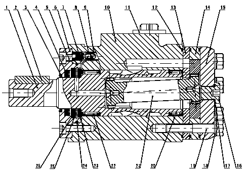
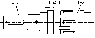
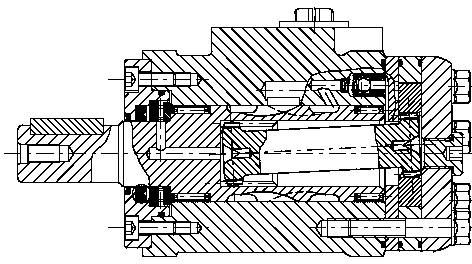
[0022] The basic structure of the shaft valve distribution cycloid hydraulic motor in this embodiment is as follows: figure 1 and image 3 As shown, it is basically the same as the prior art, including a front cover 6 and a body shell 10 fixed to each other, and a stator and a rotor with one end fixed to the body shell 10 through a partition plate 13 and the other end connected to the rear cover 15 The cycloidal pin-wheel pair 14 that forms, integral type turn stator pair is made up of stator 14-1 and rotor 14-2. The body shell 10 is equipped with an output shaft 1 extending from the outer end, and the inner spline of the output shaft is connected with the inner spline of the rotor through the linkage shaft 21 in transmission.

[0023] The inner hole of the body shell 10 is a through hole with the same inner diameter, and the front and rear ends of the output shaft 1 are respectively equipped with a front needle roller bearing 22 and a rear needle roller bearing 20 with the s...

Embodiment 2

[0029] The basic structure of the shaft valve distribution cycloid hydraulic motor in this embodiment is as follows: Figure 6 and Figure 7 As shown, its basic structure is the same as that of Embodiment 1, the main difference is that the cycloidal pin wheel pair is a studded rotary stator pair, consisting of a rotor 14-1', a stator 14-2' and pin teeth 14 -3', and different from the integral rotor-stator pair in Embodiment 1, in addition, the internal oil discharge check valve is located at the joint surface of the partition plate and the body shell.

[0030] Tests have proved that, because the above-mentioned embodiment has adopted a series of seemingly minor but actually effective improvement measures, the radial force bearing capacity of the hydraulic motor has been increased by nearly 40%, and the axial force bearing capacity has also been improved at the same time. Compact, small shape, good parts processing and assembly technology, so that the cost performance of tradi...


PUM


Abstract

The invention relates to a shaft valve flow distribution cycloid hydraulic motor and belongs to the technical field of hydraulic transmission detection. The motor comprises a front cover and a body shell which are connected with each other, and a cycloid pin wheel pair composed of a stator and a rotor, wherein one end of the cycloid pin wheel pair is fixedly connected with the body shell by a separation disc and the other end of the cycloid pin wheel pair is fixedly connected with a rear cover; the body shell is internally provided with an output shaft extended by the outer end; the output shaft is in transmission connection with the rotor by a linking shaft. The improvement is as follows: an inner hole of the body shell is a through hole with the same inner diameter; a front needle bearing and a rear needle bearing which have the same outer diameter are arranged on the front part and the rear end of the output shaft respectively; the length of the front needle bearing is longer than that of the rear needle bearing; a shaft shoulder, which corresponds to the front end of the front needle bearing, of the output shaft is abutted against a rear retainer ring of a plane thrust bearing. According to the shaft valve flow distribution cycloid hydraulic motor, under the precondition of keeping a compact structure, the radial bearing capability of the hydraulic motor is improved, the axial bearing capability is also enhanced and the machining and assembling manufacturability is good.

Description

technical field [0001] The invention relates to a hydraulic motor, in particular to a shaft valve distribution cycloid hydraulic motor, which belongs to the technical field of hydraulic transmission detection. Background technique [0002] The cycloidal hydraulic motor is a low-speed high-torque motor, which has the advantages of small size, high unit power density, high efficiency, and wide speed range, so it has been widely used. [0003] The basic structure of the cycloidal hydraulic motor is that the body shell or the back cover is equipped with a liquid inlet and a return port, and one end is equipped with a cycloidal pinwheel meshing pair and a flow distribution mechanism. The flow distribution mechanism can be placed before or after the cycloidal pinwheel meshing pair , generally the front one is the shaft valve distribution, the rear one is the plane distribution, and the other end is equipped with the output shaft. The rotor of the cycloid pinwheel meshing pair mes...

Claims


Application Information

Patent Timeline
Patent Type & Authority Applications(China)
IPC IPC(8): F03C2/08
Inventor 王志生张智敏张常青盛玉川周峰
Owner ZHENJIANG DALI HYDRAULIC MOTOR
Why Eureka
Try Eureka