
Water-lubricated air pump

A water-lubricated and air-pump technology, applied to pump components, variable-capacity pump components, liquid variable-capacity machinery, etc., can solve problems such as corrosion, deformation, wear, smog, and performance degradation, so as to ensure reliability and energy saving , prevent direct contact, prevent the effect of dust intrusion

Inactive Publication Date: 2014-03-12
深圳市中海电新能源有限公司
View PDF6 Cites 1 Cited by
  • Summary
  • Abstract
  • Description
  • Claims
  • Application Information

AI Technical Summary

Problems solved by technology

[0004] But the lubricant that the air pump of existing structure uses generally all is to use air compressor machine oil or other lubricating oil etc., the air pump that uses prior art lubricating oil can produce natural wear and tear because of long service life, especially with apron Under the viscous resistance of lubricating oil and long-term immersion, the air pump will produce corrosion, deformation and accelerated wear. The original functions of some vulnerable parts cannot play their role normally, and the performance will gradually decline.
This will cause a lot of failures, mainly as follows: 1. The wind power of the air pump gradually decreases, including the ability of air suction and air discharge; 2. The air pump has oil leakage; 3. The noise of the air pump is loud; 4. The air pump does not rotate Flexible, sometimes stuck or frequently stuck, accompanied by the sound of "哜哜" from strong friction
At the same time, the failure of the existing lubricating oil due to its poor lubrication is mainly manifested as: the air pump is easy to spray oil through the air outlet, and the blown air often contains smoke

Method used


Image

  • Water-lubricated air pump
  • Water-lubricated air pump
  • Water-lubricated air pump

Examples


Embodiment 1

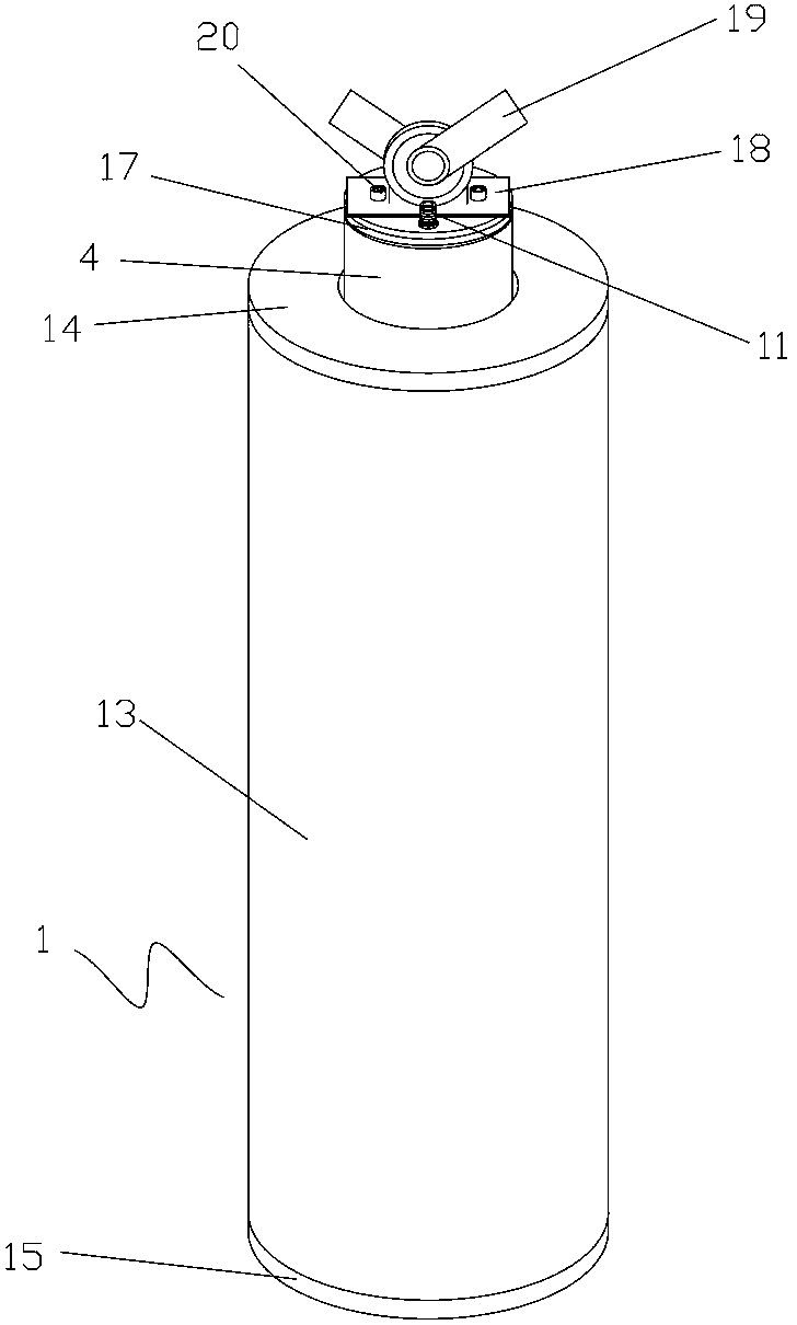
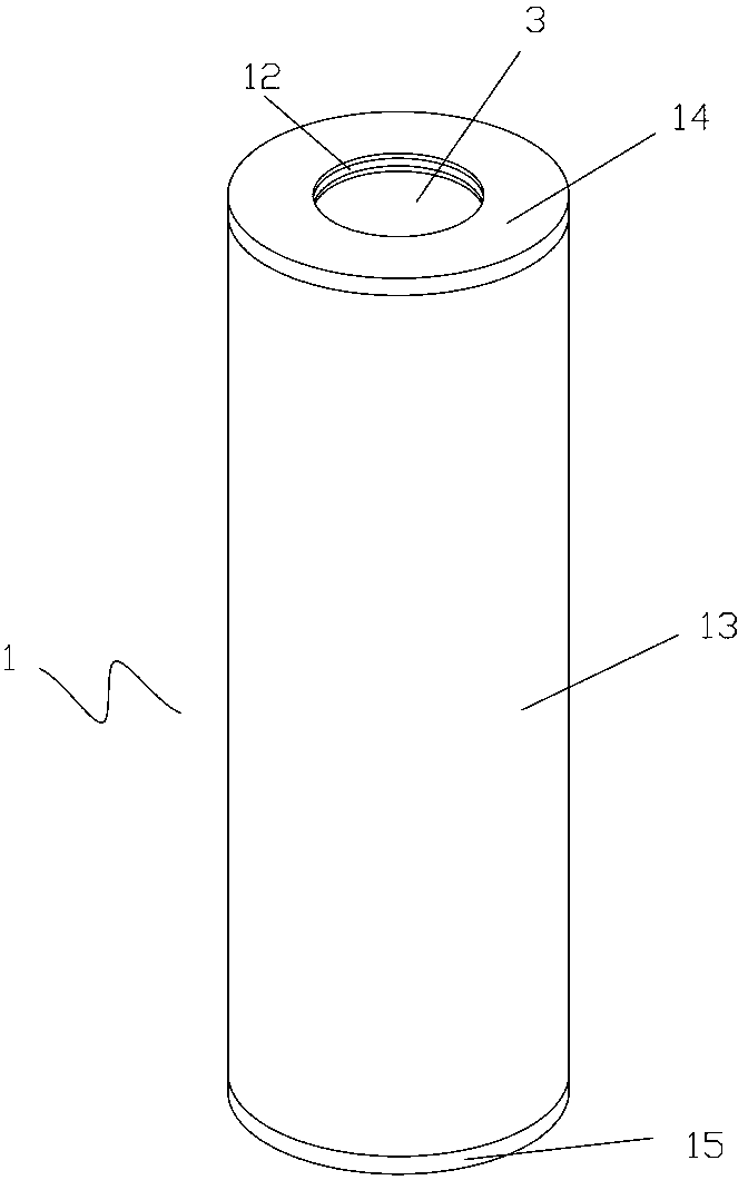
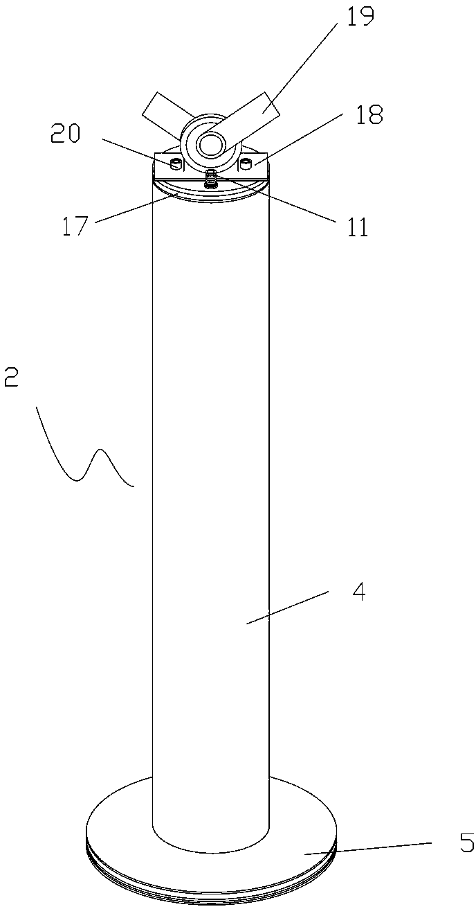
[0022] The water-lubricated air pump described in this embodiment 1, such as figure 1 , figure 2 , image 3 , Figure 4 , Figure 5 , Image 6 As shown, it includes a pump body 1 and a piston pump 2 which is installed and movable in cooperation with the pump body. The water lubricant is placed in the lower part of the pump body. The pump body and the piston pump are lubricated and matched with water lubricant. There is an air intake port 3. The piston pump is composed of a piston rod cylinder 4 and a piston 5 connected with the piston rod cylinder; the piston is equipped with an anti-wear rubber ring 6 to prevent the reciprocating movement of the piston from wearing the cylinder wall of the pump body. The piston A piston ring groove 7 is provided on the piston, and a sealed compressed air rubber ring 8 that cooperates with the piston ring groove and can be movably sealed is provided on the piston. The piston is provided with a piston air inlet 9 through the piston ring groove t...


PUM


Abstract

The invention discloses a water-lubricated air pump. The water-lubricated air pump comprises a pump body and a piston pump which is mounted and moves in a manner of being matched with the pump body, wherein the pump body and the piston pump are matched under the lubrication action of a water lubricant; the pump body is provided with an air inlet; the piston pump is composed of a piston draw rod cylinder body and a piston connected with the piston draw rod cylinder body; the piston is provided with an anti-abrasion rubber ring for preventing the cylinder wall of the pump body from abrasion caused by reciprocation of the piston; the piston is provided with a piston ring groove; the piston is provided with a compressed air sealing rubber ring which is matched with the piston ring groove and can realize movable sealing; the piston is provided with a piston air inlet extending from the piston ring groove to the bottom of the piston; the piston is provided with a compressed air inlet communicated with the piston draw rod cylinder body; and the piston draw rod cylinder body is provided with a compressed air outlet. The water-lubricated air pump uses water as the lubricant; due to the presence of a lubricating water film, direct contact of piston surfaces can be prevented, thereby reducing friction force and decreasing abrasion; and the water film can also play a cooling role, a sealing role and a washing role. In use, water and air can be automatically separated.

Description

Technical field [0001] The present invention relates to the technical field of air pumps, in particular to a water lubricated air pump that uses water lubrication as a lubricant and can generate a large amount of compressed air. Background technique [0002] Air pumps are generally powered by manpower or electricity. Generally, electric air pumps are used in the mechanical field, and electric air pumps are air pumps powered by electricity. The existing air pump mainly includes a pump body and a cylinder. The cylinder is provided with a connecting rod, a piston barrel, a piston, an air inlet and an air outlet. The cylinder is arranged in the pump body. The connecting rod in the cylinder drives the piston in the cylinder to reciprocate under the action of external force. During the reciprocating motion, the piston sucks air from the intake port and compresses the gas absorbed in the cylinder and is compressed. The gas is pushed to the outlet, and the compressed gas rushes out of ...

Claims


Application Information

Patent Timeline
Patent Type & Authority Applications(China)
IPC IPC(8): F04B39/02
Inventor 冯柯霖
Owner 深圳市中海电新能源有限公司
Learn More