
Floating type double-layer back plate brake pad

A brake pad, floating technology, applied in the direction of brake parts, etc., can solve the problems of not being able to obtain the maximum effective friction area, the service life of the brake pad, and the uneven braking pressure, etc., to achieve simple structure, reduce noise, The effect of equalizing brake pressure

Inactive Publication Date: 2014-03-12
BEIJING TIANYISHANGJIA NEW MATERIAL
View PDF6 Cites 4 Cited by
  • Summary
  • Abstract
  • Description
  • Claims
  • Application Information

AI Technical Summary

Problems solved by technology

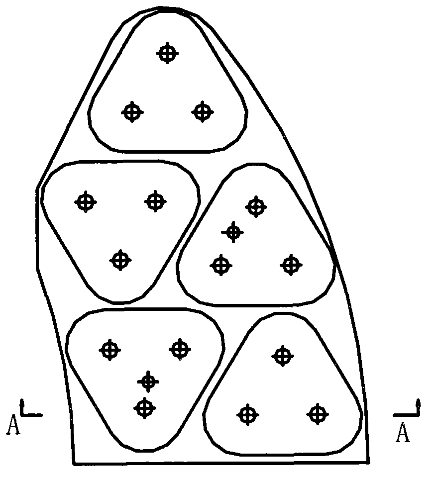
[0003] At present, in the braking system of the high-speed train disc brake device, the existing brake pad structure is as attached figure 1 , figure 2 As shown, since the friction block of the brake pad is welded or riveted to the steel back and the dovetail, there is neither relative rotation nor floating between the friction block and the steel back, so that the braking pressure of each friction block on the brake disc Unbalanced, the maximum effective friction area cannot be obtained, the thermal load is too large during braking, and the service life of the brake pads is reduced

Method used


Image

  • Floating type double-layer back plate brake pad
  • Floating type double-layer back plate brake pad
  • Floating type double-layer back plate brake pad

Examples


Embodiment Construction

[0032] The present invention will be described in detail below in conjunction with the accompanying drawings and embodiments.

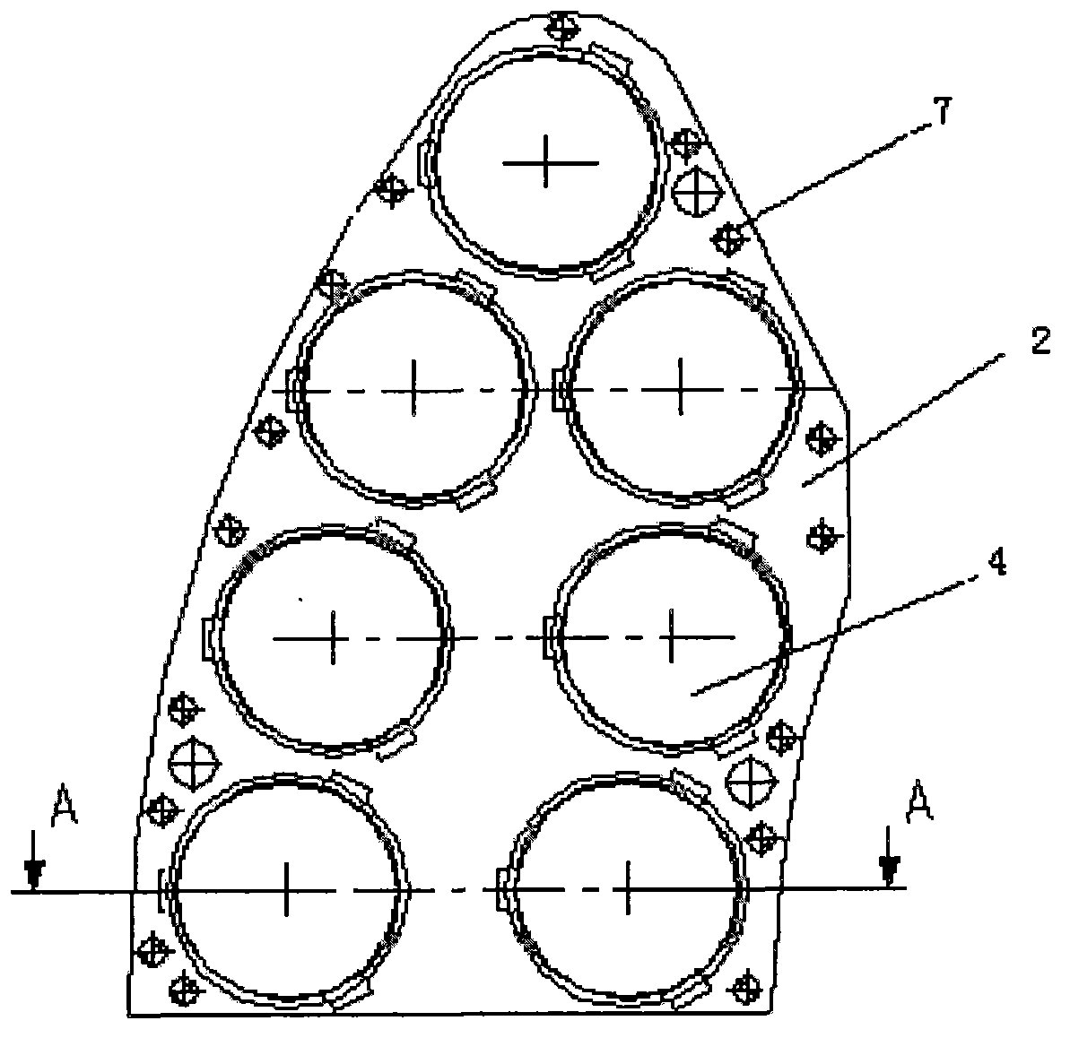
[0033] Such as Figure 3-6 As shown, the present invention includes a brake pad thick back plate 1, a brake pad thin back plate 2, several elastic pads 3, several brake pad friction blocks 4, a dovetail 5, several rivets 6, and several electric welding points 7.

[0034] Such as Figure 7-8 As shown, the arc-shaped sole structure of the thick back plate 1 of the brake pad of the present invention is made of steel material. The installation hole 102 of the brake pad friction block 2, the through hole 103 through which the guide and fastening connector of the brake pad friction block 2 passes, and the positioning hole 104 for realizing installation and positioning with the thin back plate 2.

[0035] Such as Figure 9-10 As shown, the elastic pad 3 of the present invention is stamped and formed from a high-temperature resistant alloy stainless spring...


PUM


Abstract

The invention relates to a floating type double-layer back plate brake pad which is characterized by comprising a pad thick back plate, a pad thin back plate, a dovetail element, a plurality of pad friction blocks and a plurality of elastic pads. The pad thick back plate is of an arc-shaped semi-sole structure; the elastic pads are provided with spherical supporting faces; the pad friction blocks are provided with spherical supporting faces and fastening connecting elements; the elastic pads enable the friction blocks to be adjusted in an elastic mode in the vertical direction relative to the pad thick back plate and the pad thin back plate; the spherical supporting faces of the elastic pads and the spherical supporting faces of the friction blocks can rotate; the friction blocks are cylindrical, and mutual positioning of the friction blocks in an installation plane is achieved in the circumference direction by means of three evenly distributed convex keys on a round back plate and three evenly distributed key grooves in the pad thin back plate. Compared with an existing structure, in braking of a train, the maximum contact friction area can be obtained due to pads and a brake disc, braking is stable, the functions of damping, shock absorbing, denoising, heat dissipation and the like are achieved, the friction blocks and the elastic pads can be replaced, train operation cost is reduced, and the floating type double-layer back plate brake pad can be widely applied to braking systems of high-speed trains.

Description

technical field [0001] The invention relates to a disc brake device, in particular to a double-layer back plate brake pad. Background technique [0002] Due to the high speed level of high-speed trains, the braking energy is relatively large. When braking, the heat load between the brake pad and the brake disc is relatively large: not only the friction block of the brake pad is required to be wear-resistant, high temperature resistant, and low-noise, but also a good contact between the friction block and its installed parts is required. Thermal conductivity and load balancing performance, etc. [0003] At present, in the braking system of the high-speed train disc brake device, the existing brake pad structure is as attached figure 1 , figure 2 As shown, since the friction block of the brake pad is welded or riveted to the steel back and the dovetail, there is neither relative rotation nor floating between the friction block and the steel back, so that the braking pressu...

Claims


Application Information

Patent Timeline
IPC IPC(8): F16D65/04
Inventor 吴佩芳
Owner BEIJING TIANYISHANGJIA NEW MATERIAL
Learn More