High-isolation voltage electric-light-electric isolation structure

A high isolation, electrical isolation technology, applied in the field of electrical isolation, can solve the problems of increased isolation voltage, weak electrical signal, unable to meet demand, etc., to achieve the effect of increasing isolation voltage, large isolation voltage, and increasing spacing

Inactive Publication Date: 2014-03-12
THE 44TH INST OF CHINA ELECTRONICS TECH GROUP CORP
View PDF4 Cites 4 Cited by
  • Summary
  • Abstract
  • Description
  • Claims
  • Application Information

AI Technical Summary

Problems solved by technology

[0003] In actual engineering, the potential difference between the front and rear circuits may reach tens of thousands of volts or even tens of thousands of volts. At the same time, there are strict restrictions on the volume of the electrical isolation device, which requires the electrical-optical-electrical isolation structure to have a high isolation voltage at the same time. and miniaturization features, a typical existing solution such as figure 1 shown, using figure 1 In the scheme, in order to improve the isolation voltage of the electrical-optical-electrical isolation structure, the electric field strength between the front and rear circuits is generally reduced by increasing the distance between the light source chip and the photodetection chip, and between the light source chip and the photodetection chip. The spaces between and around the two are filled with insulating light-conducting glue with high dielectric strength to improve the breakdown resistance of the electrical-optical-electrical isolation structure; the existing problem is: in theory, the closer the distance between the light source chip and the light detection chip Larger, the isolation voltage of the electrical-optical-electrical isolation structure is also higher, but in practical applications, the amount of light emitted by the light source chip and irradiated on the photodetector chip will decrease with the increase of the distance. After the isolation voltage of the electrical isolation structure is increased to more than 10,000 volts, if the spacing continues to increase, the electrical signal converted by the photodetection chip will be too weak to meet the demand, thus causing a bottleneck for further improvement of the isolation voltage

Method used


Image

  • High-isolation voltage electric-light-electric isolation structure
  • High-isolation voltage electric-light-electric isolation structure
  • High-isolation voltage electric-light-electric isolation structure

Examples


Embodiment

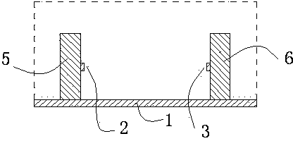
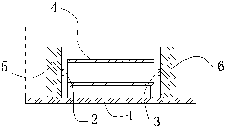
[0016] In the prior art, the distance between the light source chip 2 and the light detection chip 3 is generally set at about 1.8 mm. At this time, the isolation voltage of the electrical-optical-electrical isolation structure is about 10,000 volts. If the light source chip 2 and the optical detection chip are further increased 3, the electrical signal converted by the light detection chip 3 weakens rapidly. When the light source chip 2 and the light detection chip 3 increase to more than 2.2 mm, the electrical signal converted by the light detection chip 3 will attenuate to a level that cannot meet the demand.

[0017] By adopting the solution of the present invention, the distance between the light source chip 2 and the light detection chip 3 can be extended to more than 6 mm, and the isolation voltage can reach more than 30,000 volts, and has the potential for further improvement.


PUM


Abstract

A high-isolation voltage electric-light-electric isolation structure comprises a light source chip and a light detection chip which are arranged by being opposite in position; the space between the light source chip and the light detection chip and the space around the light source chip and the light detection chip are filled by insulation light guide glue; the innovative points are that a light guide tube is arranged between the light source chip and the light detection chip; an inner hole of the light guide tube, the light source chip and the light detection chip are arranged by being aligned; insulation light guide glue is injected in the light guide tube of which the dielectric strength is greater than that of the insulation light guide glue. The high-isolation voltage electric-light-electric isolation structure has the beneficial effects that the problem that the light quantity reaching the light detection chip is reduced because of the rising of an isolation voltage is solved, and the electric-light-electric isolation structure can obtain the larger isolation voltage.

Description

technical field [0001] The invention relates to an electrical isolation technology, in particular to an electrical-optical-electrical isolation structure with high isolation voltage. Background technique [0002] The basic principle of the electrical-optical-electrical isolation structure is: the light source chip converts the electrical signal of the front-stage circuit into an optical signal, and the optical signal is collected by the light detection chip and converted into an electrical signal and then output to the subsequent circuit, thereby realizing the front-end circuit. electrical isolation. This electrical-optical-electrical isolation structure can be used in devices such as photocouplers and photoelectric sensors. [0003] In actual engineering, the potential difference between the front and rear circuits may reach tens of thousands of volts or even tens of thousands of volts. At the same time, there are strict restrictions on the volume of the electrical isolati...

Claims


Application Information

Patent Timeline
IPC IPC(8): H01L25/16
Inventor 李冰徐道润陈春霞欧熠龚磊李祖安张佳宁李洪玉谢俊聃成精折曾铮肖清惠
Owner THE 44TH INST OF CHINA ELECTRONICS TECH GROUP CORP
Why Eureka
Try Eureka