
internal combustion engine

A technology of internal combustion engine and camshaft, applied in the direction of internal combustion piston engine, combustion engine, mechanical equipment, etc., can solve the problems such as the deterioration of the working cylinder inflation principle, and achieve the effect of improving operating characteristics and high efficiency

Inactive Publication Date: 2016-09-14
VOLKSWAGEN AG
View PDF5 Cites 0 Cited by
  • Summary
  • Abstract
  • Description
  • Claims
  • Application Information

AI Technical Summary

Problems solved by technology

Due to the operation of the internal combustion engine in the Miller cycle, however, the charging of the working cylinders deteriorates in principle

Method used


Image

  • internal combustion engine
  • internal combustion engine
  • internal combustion engine

Examples


Embodiment Construction

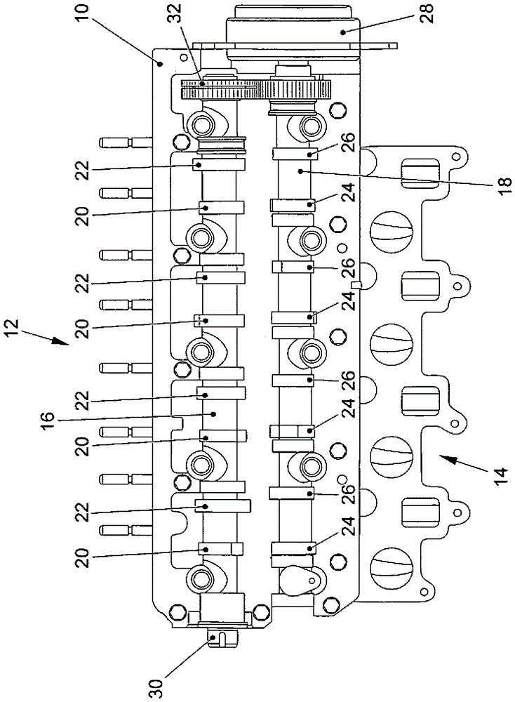
[0027] in figure 1 The embodiment of the internal combustion engine according to the present invention shown in includes a cylinder head 10 into which a working cylinder not shown in detail is integrated. In the working cylinder, there are pistons (not shown) running back and forth between top dead center (OT) and Movement between bottom dead center (UT). The cylinder head 10 includes an exhaust side 12 (where exhaust gas is directed from the working cylinder) and an intake side 14 (where fresh gas is delivered to the working cylinder).

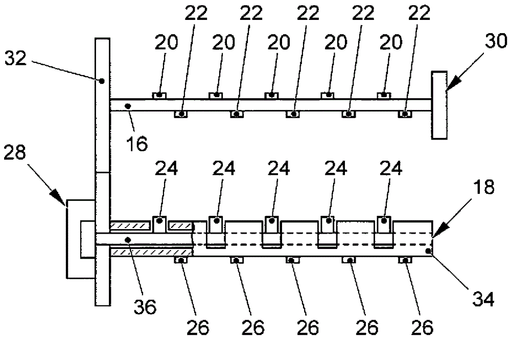
[0028] Each working cylinder is associated with two intake valves (not shown) and two exhaust valves (not shown), in which a fixed camshaft 16 and a variable camshaft 18 are provided. The fixed camshaft 16 carries an intake cam 20 respectively operating intake valves and an exhaust cam 22 respectively operating exhaust valves. Likewise, the variable camshaft 18 carries an intake cam 24 which respectively manipulates the intake valves and an exh...


PUM


Abstract

An internal combustion engine has a working cylinder with two intake valves and two exhaust valves assigned thereto. A first camshaft and a second camshaft each actuate a respective one of the intake valves and a respective one of the exhaust valves. The first camshaft is a variable camshaft with an adjuster for adjusting valve control times and includes an outer shaft, which is a hollow shaft, and an inner shaft, which is disposed within the outer shaft. The outer shaft as well as the inner shaft are rotatable by the adjuster and are rotatable relative to one another by the adjuster such that relative positions of given cams controlling given ones of the intake and exhaust valves are changeable. The second camshaft is driven by a crankshaft of the internal combustion engine and is configured as a fixed camshaft.

Description

Technical field [0001] The invention relates to an internal combustion engine, especially a diesel internal combustion engine, in particular a motor vehicle, and a method for operating such an internal combustion engine with at least one working cylinder, which is associated with at least one intake valve and an exhaust valve and in which Make the piston move back and forth (oszillierend) between top dead center (OT) and bottom dead center (UT), wherein the piston alternately follows the ventilation stroke (Ladungswechselhub) (which includes exhaust stroke and intake stroke) and work The stroke (which includes the compression stroke and the working stroke (Arbeitstakt)) drives the crankshaft, in which the intake valve and the exhaust valve are opened and closed during the ventilation stroke of the piston according to the crankshaft angle. The intake and exhaust valves are actuated by so-called "hybrid" camshaft cams. Background technique [0002] The use of a hybrid camshaft mak...

Claims


Application Information

Patent Timeline
Patent Type & Authority Patents(China)
IPC IPC(8): F02D13/02F01L1/34F01L1/047F01L1/053
CPCF01L1/047F01L1/053F01L1/0532F01L1/34F01L2001/0473F01L2001/34493F02D13/0215F02D13/0257F02D13/0265F02D13/0269F02D2013/0292Y02T10/12
Inventor A.格勒嫩迪克
Owner VOLKSWAGEN AG
Learn More