
Retaining ring and polishing head

A fixed ring and polishing head technology, which is applied in the direction of grinding devices, grinding machine tools, working carriers, etc., can solve problems such as damage, increased production costs, and decreased production efficiency, and achieve the effects of reducing production costs, reducing losses, and improving process efficiency

Active Publication Date: 2016-06-22
SHANGHAI HUALI MICROELECTRONICS CORP
View PDF6 Cites 0 Cited by
  • Summary
  • Abstract
  • Description
  • Claims
  • Application Information

AI Technical Summary

Problems solved by technology

[0004] In the chemical mechanical polishing process, it is not uncommon for the fixed ring on the polishing head to break during the polishing process and cause wafer fragmentation. Once the operation of the polishing machine cannot be detected and stopped in time, it will not only cause wafer fragmentation, but also cause wafer fragmentation. It may even cause serious damage to other components such as polishing heads and polishing pads, thereby reducing production efficiency and increasing production costs

Method used


Image

  • Retaining ring and polishing head
  • Retaining ring and polishing head
  • Retaining ring and polishing head

Examples


Embodiment Construction

[0021] The specific embodiment of the present invention will be further described in detail below in conjunction with the accompanying drawings.

[0022] It should be noted that the chemical mechanical polishing device includes a polishing disc and a polishing head, wherein the polishing head includes a wafer carrier and a fixed ring, and the wafer carrier is used to clamp a semiconductor wafer. The direction of rotation is carried out, chemical reaction and mechanical processing are carried out in this process, and the polishing process is carried out on the wafer.

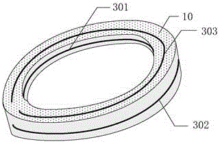
[0023] Such as Figure 2A and Figure 2B As shown, the chemical mechanical polishing fixing ring provided by the first embodiment of the present invention is used in a chemical mechanical polishing device. ) below, around the side surface of the wafer, for fixing the wafer; a frangible wire 20, which is fixed on the surface of the annular base 10, extends along the circumferential direction of the annular base ...


PUM


Abstract

The invention relates to a fixing ring used in a chemical mechanical polishing device. The chemical mechanical polishing device comprises a polishing disk and a polishing head. The polishing head comprises a chip carrier and the fixing ring, wherein the chip carrier is used for clamping a semiconductor chip, the polishing disk makes contact with the chip, and the polishing disk and the polishing head rotate in opposite directions respectively to polish the chip. The fixing ring comprises an annular base, at least one easy-to-break lead, an on-off state detection device and a signal processing device, wherein the annular base is arranged below the chip carrier, surrounds the side surface of the chip and is used for fixing the chip; the easy-to-break leads are fixed to the surface of the annular base, extend in the perimeter direction of the annular base and surround the annular base by one circle; the on-off state detection device is connected with all the easy-to-break leads respectively and sends an alerting signal when any easy-to-break lead is broken; the signal processing device is connected with the output end of the on-off state detection device and converts the alerting signal into a polishing stop signal which is used for instructing the polishing head and the polishing disk to stop rotating. The chemical mechanical polishing device can effectively lower loss of a technology caused by the fracture of the fixing ring, thereby being beneficial to the improvement of wafer preparation technological efficiency.

Description

technical field [0001] The invention relates to the technical field of semiconductor processing and manufacturing, more specifically, to a fixed ring and a polishing head used in a chemical mechanical polishing device. Background technique [0002] With the development of semiconductor manufacturing technology, while the critical dimensions of integrated circuits are getting smaller and smaller, the size of wafers is getting bigger and bigger, and the value of single wafers is getting higher and higher. Fragments will cause more and more economic losses to the factory. [0003] Chemical mechanical polishing is a method of removing solid layers to planarize the wafer surface and sharpen the pattern of metal interconnects. Typically, it employs a rotating polishing pad containing a chemically reactive slurry to polish the surface of the wafer. The wafer is placed above the polishing pad with a wafer carrier and clamped in place by the retaining ring. The fixed ring and the ...

Claims


Application Information

Patent Timeline
Patent Type & Authority Patents(China)
IPC IPC(8): B24B37/32B24B37/10B24B37/005
CPCB24B37/005B24B37/10B24B37/32
Inventor 李虎张守龙白英英赵正元
Owner SHANGHAI HUALI MICROELECTRONICS CORP
Learn More