Electromagnetism and hydraulic pressure compound brake with self power generation function and working method

A compound braking and electromagnetic braking technology, applied in electric braking systems, electric vehicles, electric energy management, etc., to reduce the dependence on the battery, solve the problem of insufficient capacity, and ensure the effect of coordinated work

Active Publication Date: 2014-03-19
郑州宇通集团有限公司
View PDF5 Cites 19 Cited by
  • Summary
  • Abstract
  • Description
  • Claims
  • Application Information

AI Technical Summary

Problems solved by technology

At present, the existing technology only studies the theory of electromagnetic/hydraulic composite braki...

Method used


Image

  • Electromagnetism and hydraulic pressure compound brake with self power generation function and working method
  • Electromagnetism and hydraulic pressure compound brake with self power generation function and working method

Examples


Embodiment Construction

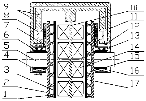
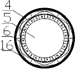
[0019] see figure 1 , the present invention includes a brake bracket 9, and the installation position and method of the brake bracket 9 and the brake caliper bracket in the traditional hydraulic braking system are the same. Two left and right wheel cylinders are installed on the brake bracket 9, a hydraulic oil circuit 11 is opened inside the brake bracket 9, and an oil inlet 12 is opened on the brake bracket 9, and the hydraulic oil circuit 11 is connected to the wheel cylinders of the left and right wheel cylinders Piston 8, there are two composite brake discs 1 between the left and right wheel cylinder pistons 8, between the two composite brake discs 1 is an electromagnetic coil bracket 10 and an electromagnetic coil 14, and the electromagnetic coil 14 is fixedly installed on the electromagnetic coil bracket 10, while the electromagnetic coil bracket 10 is fixedly connected to the brake bracket 9. There are 16-24 electromagnetic coils 14. In order to ensure the compactness...


PUM


Abstract

The invention discloses an electromagnetism and hydraulic pressure compound brake with the self power generation function and a working method. A hydraulic oil circuit is arranged in a braking support, and is connected with a left wheel cylinder piston and a right wheel cylinder piston, two compound brake disks are arranged between the left wheel cylinder piston and the right wheel cylinder piston, an electromagnetic coil is arranged between the two compound brake disks, and faces the electromagnetic braking surfaces of the compound brake disks, copper claddings are arranged on the electromagnetic braking surfaces respectively, each copper cladding is parallel to the cross section of the electromagnetic coil, an electromagnetic gap is reserved between each copper cladding and the cross section of the electromagnetic coil, the size of each electromagnetic gap ranges from 1mm to 2mm, a rotary shaft is fixedly connected with the centers of the compound brake disks, the rotary shaft, an automobile tire and a transmission shaft are connected together, permanent magnets are fixedly embedded into the rotary shaft, the magnetic poles of the permanent magnets are arranged in a staggered mode, a power generation stator coil is arranged outside the permanent magnets, the size of a gap formed between the power generation stator coil and each permanent magnet ranges from 1mm to 2mm, the rotary shaft and the compound brake disks rotate synchronously, the permanent magnets carry out power generation by cutting the magnetic field of the power generation stator coil, generated electric currents serve as field currents of the electromagnetic coil after being processed through rectification and voltage stabilization, and self energy supply is achieved.

Description

technical field [0001] The invention relates to a brake device of a passenger car, in particular to an electromagnetic-hydraulic composite brake with self-generating function. Background technique [0002] At present, the braking system of passenger cars is basically realized through friction braking through hydraulic power assist. Dynamic heat failure, wading failure, long braking response time, high maintenance cost, friction dust pollution and other problems. [0003] In order to overcome the shortcomings of the current hydraulic braking system, combining the hydraulic system with the non-contact electromagnetic braking system, using electromagnetic braking to divert the energy of the vehicle braking system is a direction for the development of the braking system. Due to friction braking and electromagnetic braking The principle of braking, the material of the brake disc, the clearance requirements between the brake disc and the friction block or the brake disc and the e...

Claims


Application Information

Patent Timeline
IPC IPC(8): B60L7/24
CPCY02T10/7241Y02T10/72
Inventor 何仁刘学军
Owner 郑州宇通集团有限公司
Why Eureka
Try Eureka