Regenerative system of turbogenerator unit and operation method thereof

A technology of steam turbine generator set and heat recovery system, which is applied in the direction of steam generation, steam engine device, machine/engine, etc. It can solve the problems of increased resistance of water supply system, decrease of unit efficiency, increase of investment cost, etc., and achieves reduction of water supply pressure Loss, operation safety, and the effect of improving drying output

Active Publication Date: 2014-03-19
王振宇
View PDF7 Cites 8 Cited by
  • Summary
  • Abstract
  • Description
  • Claims
  • Application Information

AI Technical Summary

Problems solved by technology

[0007] 1. This technology needs to connect a "final feed water heater" in series outside the conventional water supply system, so that the resistance of the water supply system increases under various operating conditions of the unit, resulting in energy waste. The "final feed water heater" needs to be put into operation, and the boiler feed water must also pass through the heater, which inevitably leads to a reduction in unit efficiency
[0008] 2. This technology needs to connect a "final feed water heater" in series in addition to the conventional water supply system, which greatly increases the investment cost; and some power stations themselves are designed to make full use of the space, and the on-site equipment is compactly arranged, so it is not possible to install another The conditions of the final stage feedwater heater with large weight and size cause limitations in the application of this technology

Method used


Image

  • Regenerative system of turbogenerator unit and operation method thereof
  • Regenerative system of turbogenerator unit and operation method thereof
  • Regenerative system of turbogenerator unit and operation method thereof

Examples


Embodiment Construction

[0030] The present invention will be described in further detail below in conjunction with the accompanying drawings and specific embodiments, so that those skilled in the art can more clearly understand other advantages and effects of the present invention.

[0031] It should be noted that the structures, proportions, sizes, etc. shown in the drawings of the specification are only used to cooperate with specific implementation methods, so that those skilled in the art can understand the concept of the present invention more clearly, and are not intended to limit the scope of protection of the present invention. . Any structural modification, change in proportional relationship or size adjustment should still fall within the protection scope of the present invention, provided that it does not affect the function and purpose of the present invention.

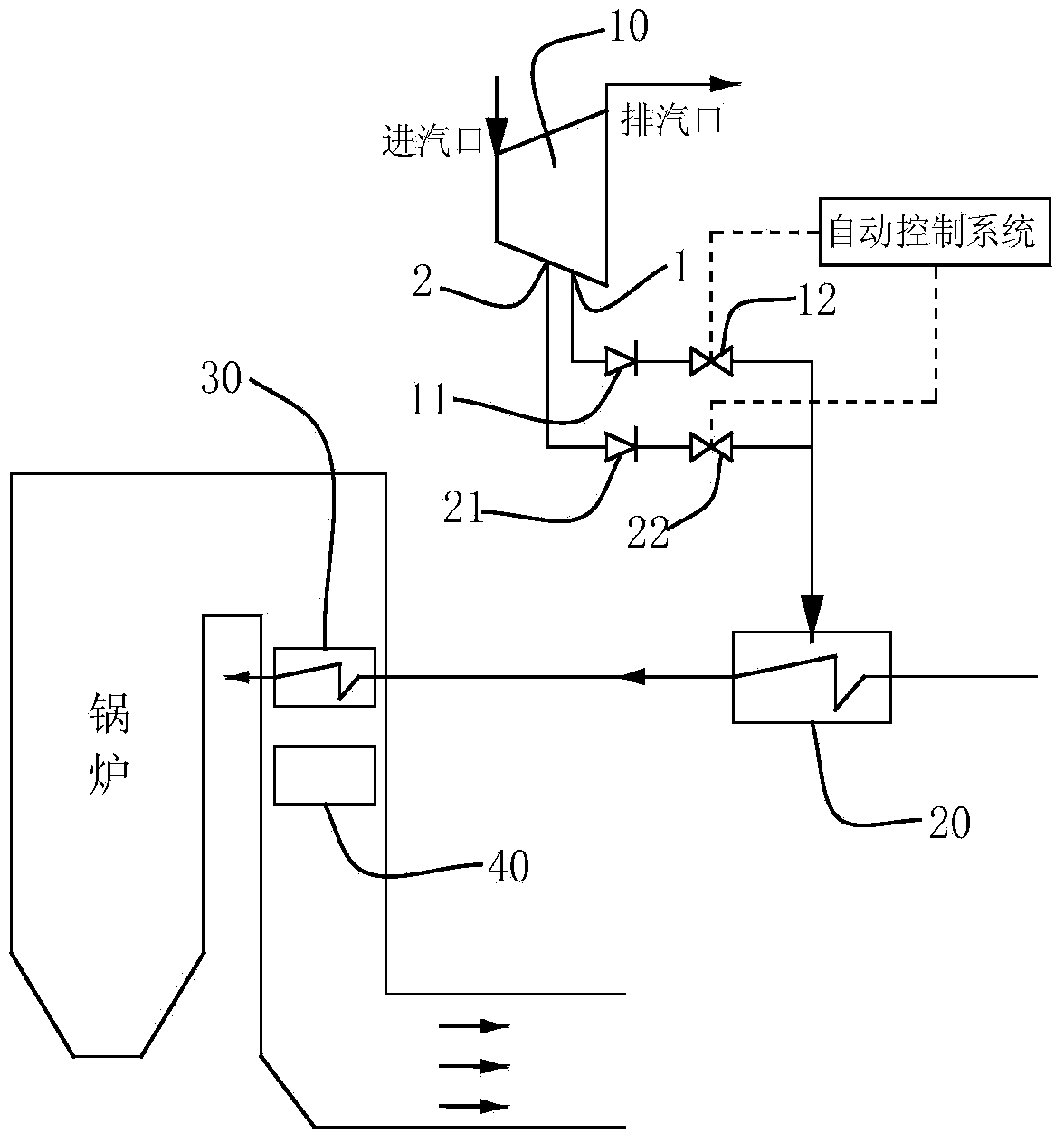
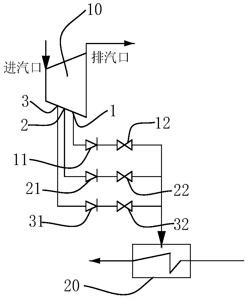
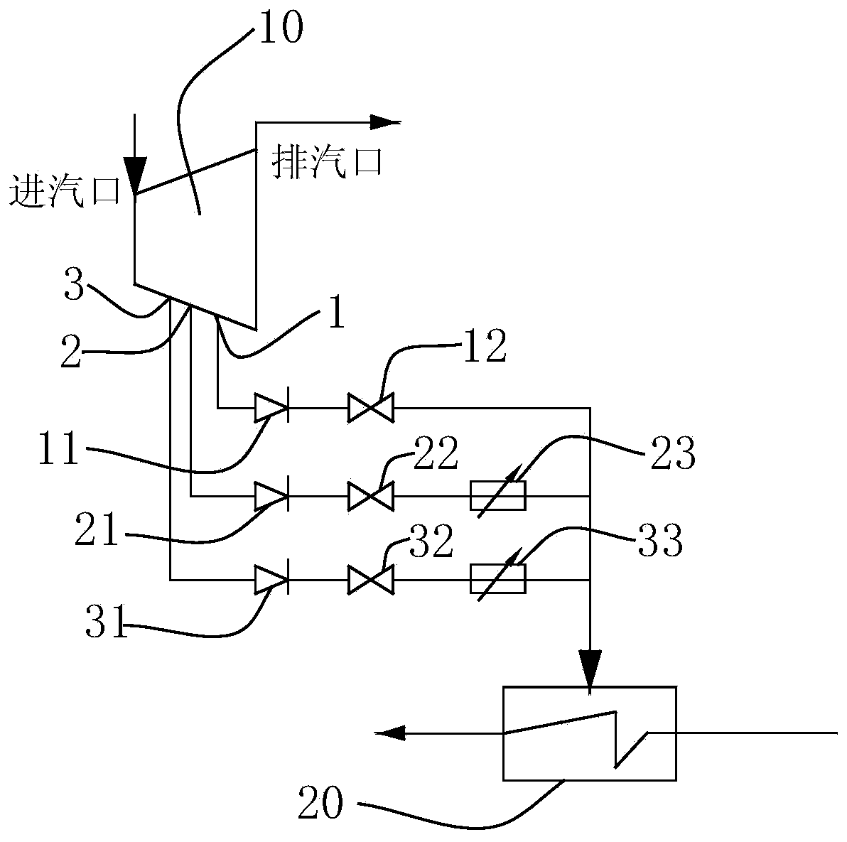
[0032] like figure 1 As shown, a steam turbine generator unit heat recovery system of the present invention includes a high-pr...


PUM


Abstract

The invention discloses a regenerative system of a turbogenerator unit and an operation method thereof. The system comprises a high-pressure cylinder and a high-pressure heater, wherein an steam exhaust port and a plurality of high-pressure steam extraction ports whose steam extraction pressure is increased sequentially are formed in the high-pressure cylinder, the high-pressure steam extraction ports are connected with the same high-pressure heater through high-pressure steam extraction pipelines, and an extraction check valve and an isolated valve are arranged on each high-pressure steam extraction pipeline. When the turbogenerator unit operates at a rated load, a first high-pressure steam extraction port with the lowest steam extraction pressure supplies steam for the high-pressure heater, and the steam extraction pressure at the time is set to be P0; when the turbogenerator unit operates in a state lower than the rated load, a high-pressure steam extraction port with steam extraction pressure less than or equal to P0 or closer to P0 is selected to supply steam for the high-pressure heater, and the isolated valves on other high-pressure steam extraction pipelines are switched off. According to the regenerative system of the turbogenerator unit and the operation method thereof, a denitration system can operate normally when the unit operates at a low load, the boiler feeding temperature is increased, and the thermodynamic cycle efficiency of the unit is improved accordingly.

Description

technical field [0001] The invention relates to a steam turbine generator set, in particular to a steam turbine generator set heat recovery system for heating boiler feed water by steam extraction from a steam turbine generator set and an operating method thereof. Background technique [0002] The steam turbine heat recovery system usually extracts some steam from several intermediate stages of the steam turbine and sends it to the feed water heater for heating the boiler feed water, thereby increasing the average temperature of the working fluid in the heat absorption process in the boiler to improve the thermodynamic cycle of the unit efficiency. [0003] At the same time, the flue gas emission of coal-fired thermal power units must meet environmental protection requirements. The state stipulates that coal-fired thermal power units must be put into operation with denitrification above 50% of the rated load, and NO X The emission concentration is less than 100 mg / m3. [0...

Claims


Application Information

Patent Timeline
Patent Type & Authority Applications(China)
IPC IPC(8): F01K17/02F22D1/32
Inventor 王振宇
Owner 王振宇
Why Eureka
Try Eureka