Cooling method of turbine rotor of combustion gas turbine and cooling gas system

A gas turbine, cooling gas technology, applied in separation methods, chemical instruments and methods, mechanical equipment, etc., can solve problems such as insufficient utilization of energy, unadjustable cooling gas volume, etc., to improve combined cycle performance, improve cooling effect, optimize performance effect

Active Publication Date: 2019-05-28
HANGZHOU TURBINE POWER GRP
View PDF4 Cites 1 Cited by
  • Summary
  • Abstract
  • Description
  • Claims
  • Application Information

AI Technical Summary

Problems solved by technology

[0004] The present invention aims at the above problems, in order to solve the shortcomings of the existing turbine rotor cooling gas system that the energy is not fully utilized and the amount of cooling gas cannot be adjusted, the present invention provides a new gas turbine rotor cooling method and cooling gas system , this method can not only cool the compressor exhaust (

Method used


Image

  • Cooling method of turbine rotor of combustion gas turbine and cooling gas system
  • Cooling method of turbine rotor of combustion gas turbine and cooling gas system
  • Cooling method of turbine rotor of combustion gas turbine and cooling gas system

Examples


Example Embodiment

[0024] The technical solutions in the embodiments of the present invention will be clearly and completely described below in conjunction with the accompanying drawings in the embodiments of the present invention. Obviously, the described embodiments are only a part of the embodiments of the present invention, rather than all the embodiments. Based on the embodiments of the present invention, all other embodiments obtained by those of ordinary skill in the art without creative work shall fall within the protection scope of the present invention.
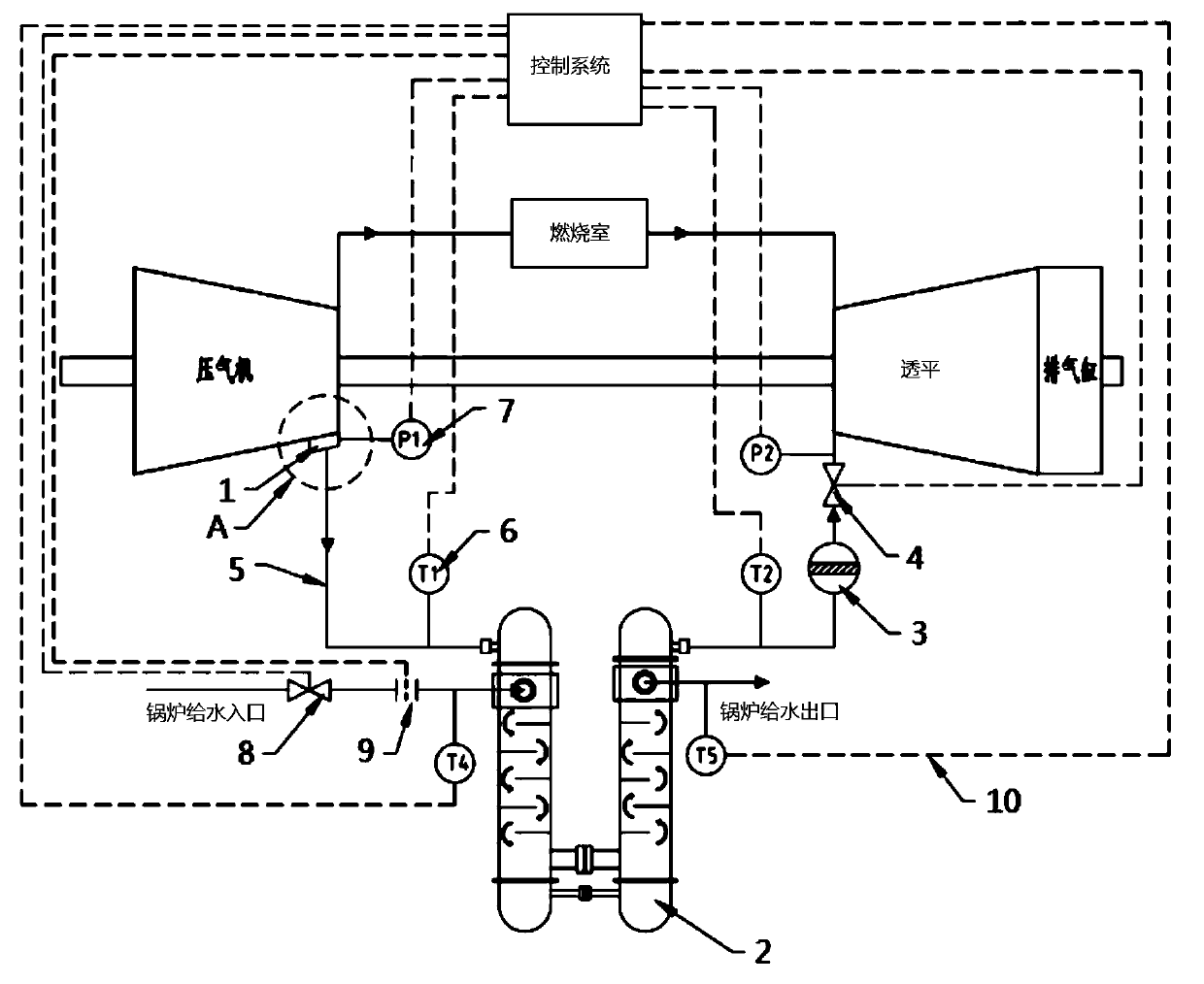
[0025] reference figure 1 As shown, a gas turbine turbine rotor cooling design is mainly composed of diffuser 1, heat exchanger 2, filter 3, air extraction regulating valve 4, air extraction pipeline 5, temperature measurement device 6, pressure measurement device 7, and water supply The regulating valve 8, the flow meter 9, and the signal line 10 are composed; the diffuser 1 is integrated on the compressor cylinder and is located at the...


PUM


Abstract

The invention discloses a cooling method of a turbine rotor of a combustion gas turbine and a cooling gas system. A gas pumping pipeline is connected between a gas compressor and a turbine, wherein agas pumping adjusting valve is arranged on the gas pumping pipeline; a temperature measuring device and a pressure measuring device are arranged at different points on the combustion gas turbine and are connected to a control system through signal circuits; the temperature measuring device and the pressure measuring device are used for transmitting detecting signals to the control system through the signal circuits; the control system is used for controlling the gas pumping adjusting valve and a water supplying adjusting valve to adjust to reach the temperature and flow rate required by gas tocool a turbine blade of the combustion gas turbine and a wheel disc; a water cooling temperature conditioning device for cooling gas is arranged between the gas compressor and the gas pumping adjusting valve on a gas pumping pipeline; the temperature T2 of cooling gas exhausted through the temperature conditioning device and fed into the turbine can be determined based on the gas temperature forcooling the turbine blade of the combustion gas turbine and the wheel disc; and the water inlet flow rate m1 of the temperature conditioning device is adjusted to control the temperature T2 of the cooling gas exhausted by the temperature conditioning device. The method and the system reach the best cooling effect with the least cooling gas volume.

Description

technical field [0001] The invention relates to the field of gas turbines, in particular to a method for cooling a turbine rotor of a gas turbine and a cooling gas system. Background technique [0002] The turbine vanes, moving blades and discs in the hot passage of the gas turbine are in a high-temperature environment. Due to the limitation of materials, they need to be cooled by cooling gas to ensure reliable operation and ensure the necessary life. Typically, the compressor exhaust (extraction air) is directed into the turbine for cooling. Under the full-load condition of the gas turbine, the temperature of the compressor exhaust (exhaust air) is relatively high, which is directly used to cool the hot passage components of the turbine, and the required flow rate is relatively large. Excessive extraction air flow rate will affect the efficiency of the unit. [0003] In addition, due to the fact that the disc clearance does not change linearly during the change of the hot ...

Claims


Application Information

Patent Timeline
IPC IPC(8): F01D5/08F01D5/18F01D21/00F22D1/16F22D5/00B01D46/00
Inventor 杨晶晶辛小鹏隋永枫孔建强但汉攀丁骏张发生蓝吉兵
Owner HANGZHOU TURBINE POWER GRP
Why Eureka
Try Eureka