
Solar flat plate collector

A solar panel and heat collector technology, applied in the field of heat collectors, can solve the problems of inconvenient processing, large combined thermal resistance and high heat transfer efficiency, and achieve the effects of cheap processing equipment, small combined thermal resistance and large contact area

Inactive Publication Date: 2014-03-19
郭强
View PDF0 Cites 4 Cited by
  • Summary
  • Abstract
  • Description
  • Claims
  • Application Information

AI Technical Summary

Problems solved by technology

The collector plates of flat-plate collectors generally have three structures: flat box type, wing-tube type and tube-sheet type. The above three structures constitute the mainstream of the plate core of today's flat-plate collectors, but the above three structures have different disadvantages , the flat box type has high heat transfer efficiency but is not easy to process. The fin tube type has a hollow fin before welding the heat collecting fin and the flow channel. It is inconvenient to process copper tubes for the channel. The tube-sheet structure uses laser or ultrasonic to weld the heat collecting fins on the flow channel. For the convenience of welding, copper pipes are also used for the flow channel, which is inconvenient to process. The air between the glass cover plate and the heat collecting fins of the above three types of flat solar panels is a whole. The heat is uneven between the upper part and the lower part, and the upper part of the glass cover has a high temperature and the heat loss to the outside is relatively large

Method used


Image

  • Solar flat plate collector
  • Solar flat plate collector
  • Solar flat plate collector

Examples


Embodiment Construction

[0021] The preferred embodiments of the present invention will be described in detail below in conjunction with the accompanying drawings, so that the advantages and features of the present invention can be more easily understood by those skilled in the art, so as to define the protection scope of the present invention more clearly.

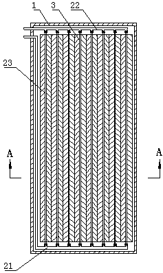
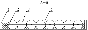
[0022] refer to Figure 1 to Figure 5 As shown, a kind of solar panel heat collector provided by the present invention includes a shell 1, and a thermal insulation board 2, a heat-absorbing plate core 3, and a high light-transmitting plate 4 are sequentially stacked in the shell, and the heat-absorbing plate core 3 includes a The heat collecting water inlet pipe 21 and the heat collecting water outlet pipe 22 at both ends, and a plurality of heat collecting pipe assemblies 23 installed between the heat collecting water inlet pipe 21 and the heat collecting water outlet pipe 22, each heat collecting pipe assembly 23 includes two The heat-collectin...


PUM


Abstract

The invention discloses a solar flat plate collector which comprises a shell. A heat insulation board, a heat absorption board core and a high transmittance board are sequentially stacked in the shell, the heat absorption board core comprises a heat collection water inlet pipe, a heat collection water outlet pipe and a plurality of heat collection rack pipe components, the heat collection water inlet pipe and the heat collection water outlet pipe are arranged at two ends of the heat absorption board core, the heat collection rack pipe components are mounted between the heat collection water inlet pipe and the heat collection water outlet pipe, each heat collection rack pipe component comprises a heat collection rack pipe and heat collection fins, two ends of each heat collection rack pipe are communicated, an arc structure is arranged on each heat collection fin and sleeved on the outer wall of each heat collection rack pipe, and the outer diameter of each arc structure is as same as that of each heat collection rack pipe. The arc structures wrap external circles of the heat collection rack pipes, the contact area of the heat collection fins and the heat collection rack pipes is large, combined heat resistance is low, and the solar flat plate collector has the advantages of inexpensiveness of processing equipment and simplicity in assembly.

Description

technical field [0001] The invention relates to the technical field of heat collectors, in particular to a solar flat plate heat collector. Background technique [0002] Because flat-panel solar water heaters can be better integrated with buildings, they are used more and more. The collector plates of flat-plate collectors generally have three structures: flat box type, wing-tube type and tube-sheet type. The above three structures constitute the mainstream of the plate core of today's flat-plate collectors, but the above three structures have different disadvantages , the flat box type has high heat transfer efficiency but is not easy to process. The fin tube type has a hollow fin before welding the heat collecting fin and the flow channel. It is inconvenient to process copper tubes for the channel. The tube-sheet structure uses laser or ultrasonic to weld the heat collecting fins on the flow channel. For the convenience of welding, copper pipes are also used for the flow...

Claims


Application Information

Patent Timeline
Patent Type & Authority Applications(China)
IPC IPC(8): F24J2/26F24J2/46F24S10/75
CPCY02E10/44
Inventor 郭强
Owner 郭强
Learn More