Bobbin-winding machine

A winding and bobbin technology, applied in the field of bobbin winding machines, to achieve the effect of stable and operation, continuous output operation, and trouble-free operation

Inactive Publication Date: 2014-03-19
MASCHINENFABRIK RIETER AG
View PDF8 Cites 8 Cited by
  • Summary
  • Abstract
  • Description
  • Claims
  • Application Information

AI Technical Summary

Problems solved by technology

Consequently, each movement of the traversing mechanism results in a certain draft

Method used


Image

  • Bobbin-winding machine

Examples


Embodiment Construction

[0018] The following is based on figure 1 The present invention will be described in more detail.

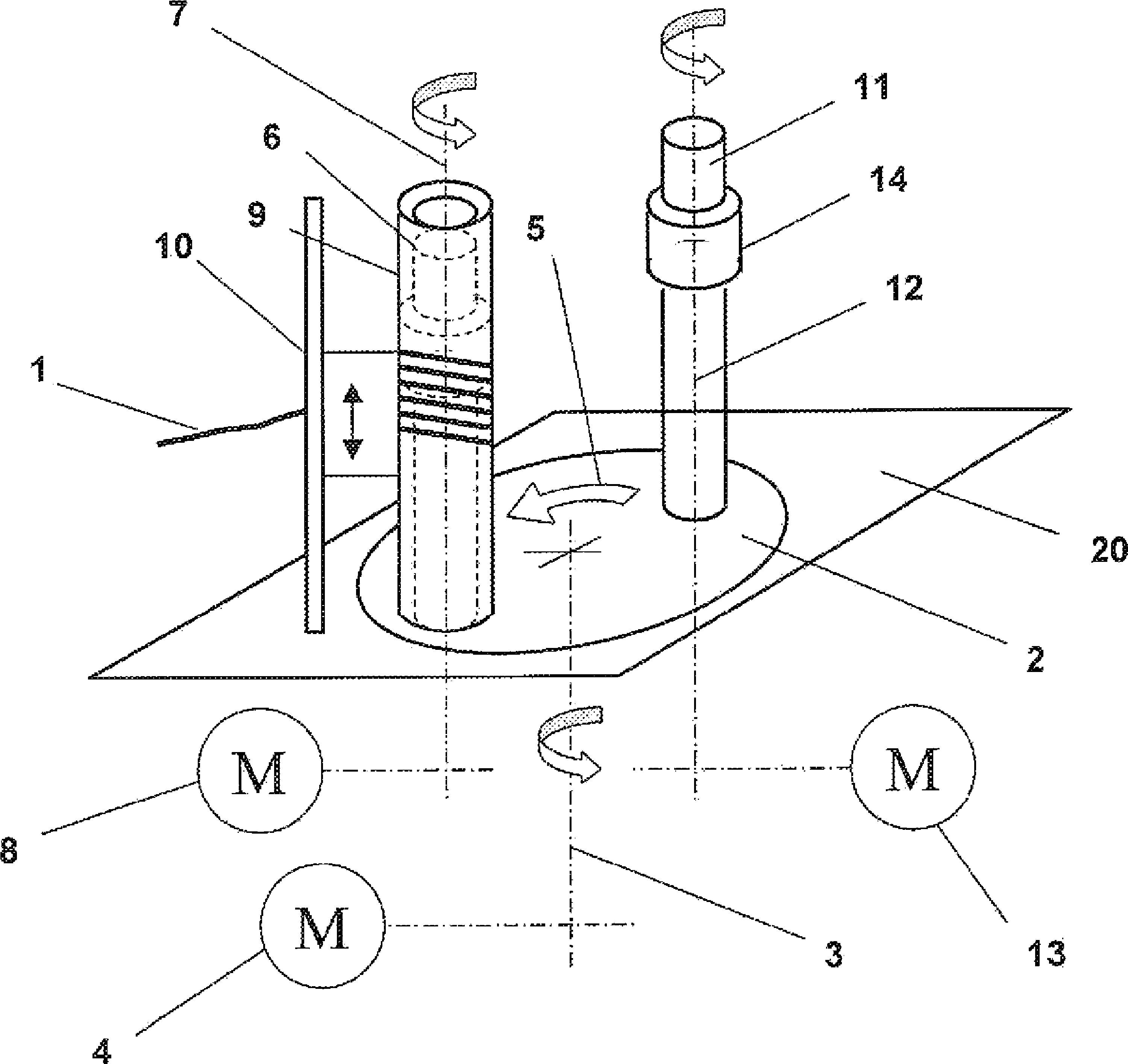
[0019] figure 1 Schematic showing the turret winding head. The turret base plate 2 is held and rotatably mounted in the frame 20 . The turret base plate 2 is arranged horizontally and has a vertical axis of rotation 3 . The turret base plate 2 is rotated about the axis of rotation 3 in steps of 180° according to the arrow 5 by means of the drive 4 . A first spindle 6 and a second spindle 11 are held and rotatably mounted in the turret base plate 2 . The first spindle 6 is connected to a drive 8 via an axis of rotation 7 . The second spindle 11 is connected to a drive 13 via an axis of rotation 12 . The first spindle 6 and the second spindle 11 are operated independently of each other. Advantageously, the drives 8 , 13 of the first spindle 6 and of the second spindle 11 are equipped with frequency controllers.

[0020] exist figure 1 In the illustration of , the first sp...


PUM


Abstract

The invention relates to an apparatus and a method for winding roving (1) onto bobbin tubes (9) by way of a turret winding head. The turret winding head comprises a turret base plate (2) having a first spindle (6) and a second spindle (11) for receiving the bobbin tubes, said spindles being held in the turret base plate and having a longitudinal axis (7, 12). The turret base plate (2) and the spindles (6, 11) are each provided with a separate drive (4, 8, 13). The longitudinal axes (7, 12) of the spindles (6, 11) are oriented in the vertical direction.

Description

technical field [0001] The invention relates to an apparatus for winding roving onto bobbins using a turret winding head. Background technique [0002] Roving frames are used to produce so-called rovings or slivers, which are used as feed material for spinning fiber yarns, eg on ring spinning machines. The roving used as feed material for ring spinning machines is usually produced from drafter slivers which are drawn on the drafting device of the roving frame and subsequently slightly twisted so that the roving can be formed without The drafting method is wound onto the bobbin. The twist applied must be only to such an extent that the cohesion of the fibers is strong enough for rewinding and unwinding and bobbin delivery. On the other hand, with regard to the drafting on the ring spinning machine, this so-called delivery twist must be low so that drafting defects do not occur in the further production process. Despite the applied factory twist, the roving must be able to ...

Claims


Application Information

Patent Timeline
Patent Type & Authority Applications(China)
IPC IPC(8): B65H54/54B65H54/74B65H67/048
CPCB65H2701/31B65H54/543B65H54/74B65H67/048B65H54/28D01H1/36D01H7/92
Inventor C.格里伊斯沙梅
Owner MASCHINENFABRIK RIETER AG
Why Eureka
Try Eureka