Small high anti-clogging drip irrigation emitter

An irrigator, high-resistance technology, applied in watering devices, horticulture, botanical equipment and methods, etc., can solve the problems of increased clogging risk and complex clogging mechanism of the irrigator, and achieve the design of hydraulic and anti-clogging structures. Coordinate, enhance the effect of hydraulic shear force, improve cleaning ability and anti-clogging performance

Active Publication Date: 2016-01-20
CHINA AGRI UNIV
View PDF9 Cites 0 Cited by
  • Summary
  • Abstract
  • Description
  • Claims
  • Application Information

AI Technical Summary

Problems solved by technology

[0003] In fact, the water quality of drip irrigation water sources is relatively complex. With the increasingly severe shortage of water resources, water with high sand content, recycled water, and brackish water are usually used as irrigation water sources, which contain a large amount of solid suspended particles, salt ions, algae, and organic pollution. substances and microorganisms, etc., which will increase the risk of emitter clogging sharply and the mechanism of clogging will become more complicated

Method used


Image

  • Small high anti-clogging drip irrigation emitter
  • Small high anti-clogging drip irrigation emitter
  • Small high anti-clogging drip irrigation emitter

Examples


Embodiment Construction

[0016] The present invention will be described in detail below in conjunction with the accompanying drawings and embodiments.

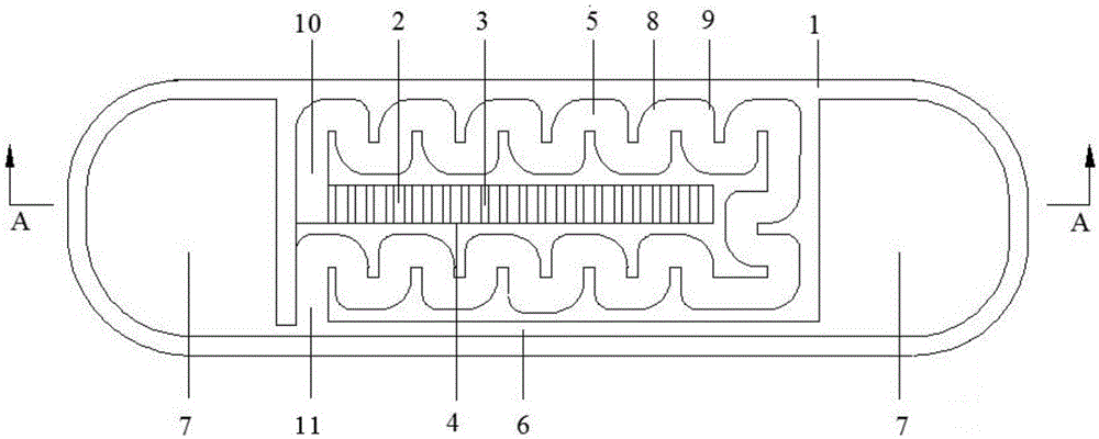
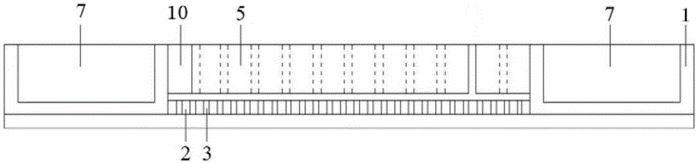
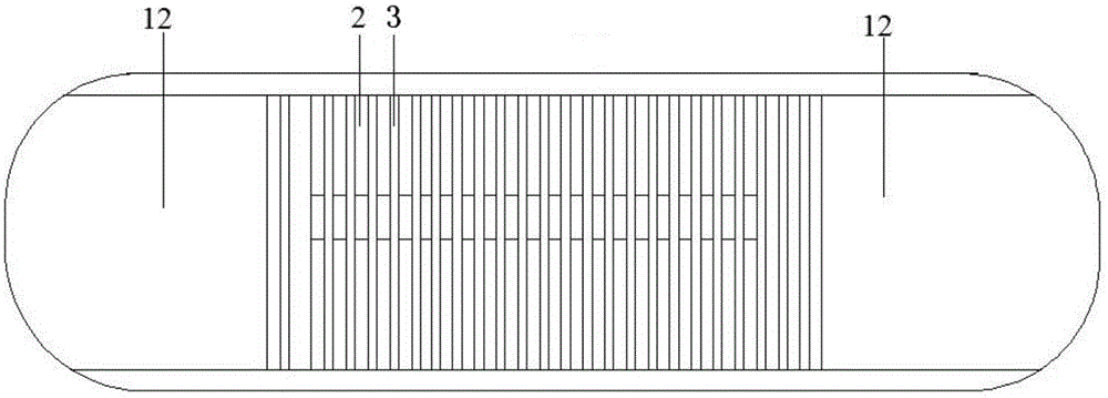
[0017] Such as figure 1 , figure 2 As shown, the present invention includes an emitter body 1, and two water outlets 7 are arranged symmetrically at both ends of the emitter body 1 . On the emitter body 1 between the two water outlets 7, a water inlet 4 is provided in the horizontal direction, and at the same time, an energy dissipation labyrinth flow channel 5 is arranged on the upper surface of the emitter body 1 located at the periphery of the water inlet 4, and the energy dissipation labyrinth flow channel One end of 5 communicates with the water inlet 4 to form a channel inlet 10 , and the other end surrounds the water inlet 4 to form a channel outlet 11 . On the upper surface of the emitter body 1 located on the side of the outlet 11 of the flow channel, there is also a drainage channel 6 extending laterally and communicating with the outlet ...


PUM


Abstract

The invention relates to a small high-blocking-resistant drip irrigation emitter which comprises an irrigation emitter body. Two water outlets are symmetrically formed in the two ends of the irrigation emitter body and a water inlet is transversely formed in the portion, between the water outlets, of the irrigation emitter body; an energy-dissipation labyrinth channel is formed in the upper surface of the irrigation emitter body, one end of the energy-dissipation labyrinth channel is communicated with the water inlet so that a channel entrance can be formed, and the other end of the energy-dissipation labyrinth channel is arranged around the water inlet so that a channel exit can be formed; a drainage channel which expands in the transverse direction and is communicated with the channel exit is formed in the upper surface of the portion, at the channel exit side, of the irrigation emitter body and is communicated with the two water outlets; a grating is arranged on the lower surface of the portion, below the water inlet, of the irrigation emitter body and is composed of a plurality of bars which are longitudinally arranged at equal intervals; the energy-dissipation labyrinth channel is of a two-row-tooth shape and twists and turns, tooth tip backwater zones and tooth tip upstream zones are formed in the bent portions in an alternative mode, a circular arc with the radius half of the width of the energy-dissipation labyrinth channel is adopted by each tooth tip upstream zone, and a circular arc with the radius equal to the width of the energy-dissipation labyrinth channel is adopted by each tooth tip backwater zone. According to the small high-blocking-resistant drip irrigation emitter, small-flow high-frequency irrigation is achieved and the small high-blocking-resistant drip irrigation emitter is highly matched with the drip irrigation pipe wall and has the high blocking-resistant performance.

Description

technical field [0001] The invention relates to the technical field of agricultural water-saving irrigation, in particular to a small-sized drip irrigation emitter with high resistance to clogging. Background technique [0002] A large number of studies at home and abroad have shown that high-frequency irrigation has a significant impact on improving crop yield, quality and water use efficiency. Since the 1980s, it has been popularized and applied in Israel, the United States and other developed countries with relatively water-saving irrigation technologies. Israeli companies such as Netafim, Plastro and EN-Tal have also produced matching small-flow emitter products, but the price is relatively expensive. Applied in the field of greenhouse crop irrigation with clean water. At present, drip irrigation with large flow rate is widely used in the field of agricultural water-saving irrigation in my country. Due to the large flow rate of the emitter, the inconsistency between the...

Claims


Application Information

Patent Timeline
Patent Type & Authority Patents(China)
IPC IPC(8): A01G25/02
Inventor 李云开冯吉
Owner CHINA AGRI UNIV
Why Eureka
Try Eureka