Magnetic rod with movable magnets and iron removal device applying magnetic rod

A magnetic bar and magnet technology, applied in the magnetic field, can solve problems such as damage, uneven distribution of magnetic force lines, weak magnetic field, etc., and achieve the effects of reduced use, simple structure, and strong magnetic force

Inactive Publication Date: 2014-03-26
廖明勇
View PDF8 Cites 9 Cited by
  • Summary
  • Abstract
  • Description
  • Claims
  • Application Information

AI Technical Summary

Problems solved by technology

Although the iron remover provided by this utility model can realize the function of continuous iron removal, this iron remover uses a permanent magnet close to the magnetic conduction cavity to make the magnetic conduction cavity generate magnetism to realize the iron removal function. The magnetic field is weak, the distribution of the magnetic force lines in the magnetic cavity is not balanced, and the permanent magnet is exposed outside the iron remover, which is easy to cause damage due to external force factors

Method used


Image

  • Magnetic rod with movable magnets and iron removal device applying magnetic rod
  • Magnetic rod with movable magnets and iron removal device applying magnetic rod
  • Magnetic rod with movable magnets and iron removal device applying magnetic rod

Examples


Embodiment 1

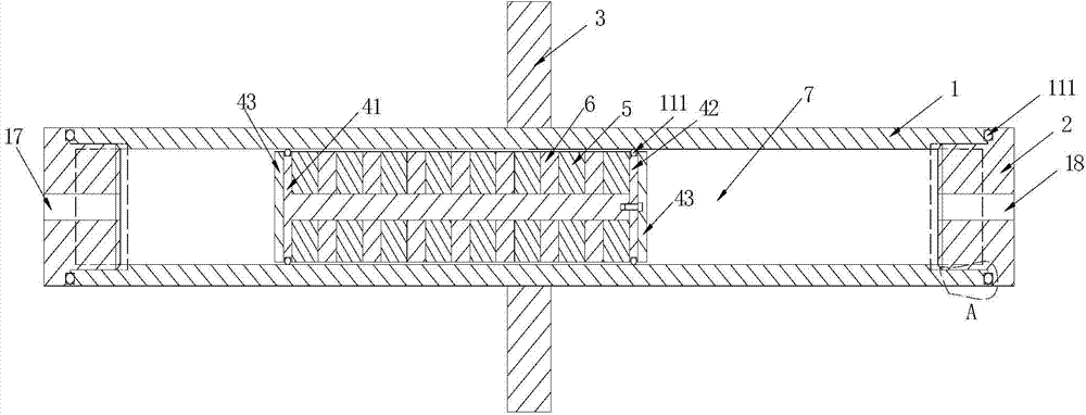
[0031] Embodiment 1: as figure 1 As shown in the magnetic bar, in the first embodiment, the shell part is composed of a cylindrical shell 1 and two sealing covers 2 . Both ends of the housing 1 are open, and an annular first sealing groove 11 is provided on the end surface. Internal threads are processed at the openings at both ends of the housing 1 . A baffle 3 is also provided on the shell 1 , and the baffle 3 is set in the middle of the shell 1 . The sealing cover 2 is a T-shaped cylindrical member, including a flange 12 and a protruding end 13 . The flange 12 is provided with a second sealing groove 14 corresponding to the first sealing groove 11 on the housing 1 . The protruding end 13 is processed with an external thread matching the internal thread at the opening of the housing 1 . Both sides of the sealing cover 2 are also provided with air intake passages, which are respectively a left air intake hole 17 and a right air intake hole 18 . A magnetic rod piston cham...

Embodiment 2

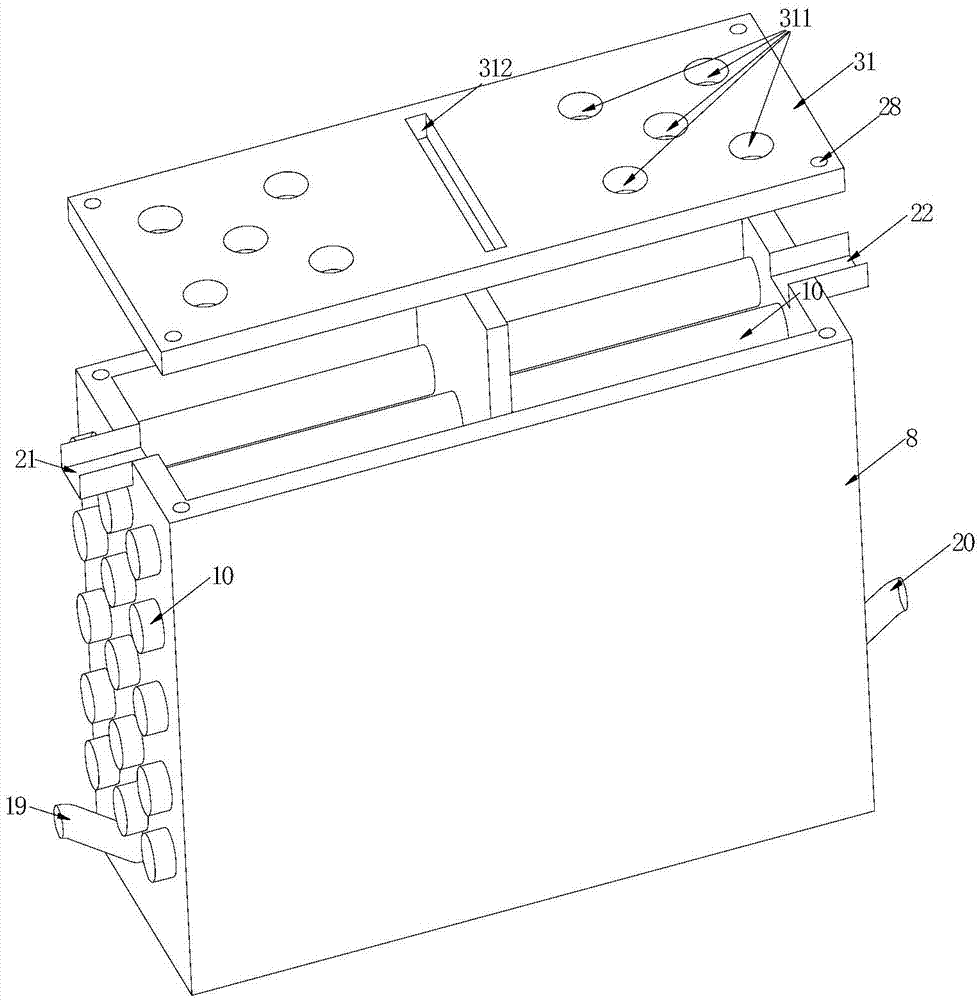
[0035] Embodiment 2: as figure 2 , 5 , 6, 7, 8, 9, a slurry iron removal device, including a working chamber 8. The working chamber 8 is a cuboid structure with an opening at the top and a partition 9 in the middle of the chamber. The height of the partition 9 is higher than that of the working chamber 8 and divides the working chamber 8 equally into two parts, which are respectively a left working chamber 81 and a right working chamber 82 . The side of the working chamber 8 is provided with 2 stock inlets, which are respectively the left stock port 19 and the right stock port 20, and the top of the working chamber 8 is provided with 2 stock outlet channels, which are respectively the left stock port 21 and the right stock port 20. The right pulp outlet channel 22, and the bottom of the working chamber 8 are also provided with two pulp return ports, which are respectively the left pulp return port 23 and the right pulp return port 24, 1 pulp inlet port, 1 pulp outlet channe...

Embodiment 3

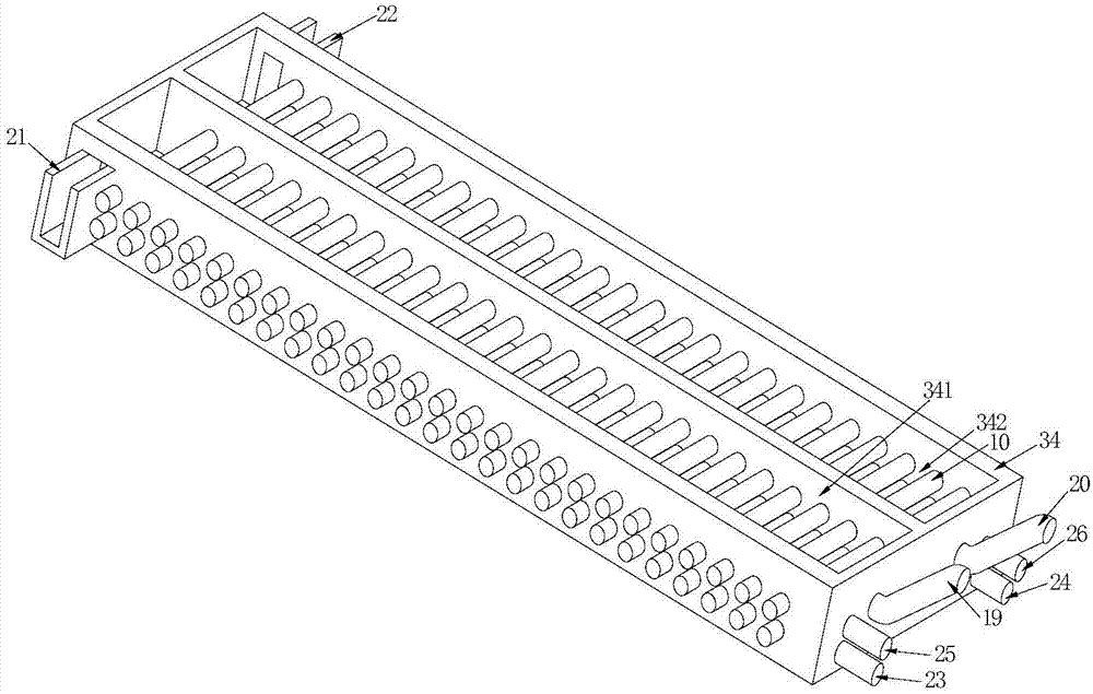
[0043] Embodiment 3: as image 3 As shown, a trough-type iron removal device includes a trough body 34 having a general trough structure, and a partition 9 is provided in the middle of the trough body 34 . The height of the partition plate 9 is flush with the tank body 34 , and the cavity of the tank body 34 is equally divided into two parts, namely the left flow groove 341 and the right flow groove 342 . The initial end of the tank body 34 is provided with two pulp inlets, which are respectively the left pulp inlet port 19 and the right pulp inlet port 20, and the end of the tank body 34 is provided with two pulp outlet channels, which are respectively the left pulp outlet channel 21 And the right pulp outlet channel 22, the end of the tank body 34 is also provided with two return ports, which are respectively the left return port 23 and the right return port 24. One stock inlet, one return port and one A group of pulp outlet flow channels is distributed symmetrically with r...


PUM


Abstract

The invention discloses a magnetic rod with movable magnets. The magnetic rod is characterized by comprising a shell part and a piston part, wherein a magnetic rod piston cavity is formed in the shell part and is a columnar space, one end of the magnetic rod piston cavity is communicated with a first air inlet channel, and the other end of the magnetic rod piston cavity is communicated with a second air inlet channel; the piston part comprises a plurality of permanent magnets, a plurality of concentrating flux plates and connecting pieces used for connecting the permanent magnets with the concentrating flux plates; the two adjacent permanent magnets are distributed in a manner that like poles repel, and each concentrating flux plate is arranged between the two adjacent permanent magnets; the piston part is arranged in the magnetic rod piston cavity, is in leak-proof fit with the magnetic rod piston cavity and does a straight reciprocating motion in the magnetic rod piston cavity. The magnetic rod with movable magnetic regions disclosed by the invention is simple in structure. The iron removal device applying the magnetic rod achieves continuous iron removal of slurry and powder, and is simpler in structure, longer in service life and high in iron removal efficiency.

Description

technical field [0001] The invention relates to the field of magnetic technology, in particular to a magnetic bar with a movable magnet and an iron removing device using the same. Background technique [0002] Most of the existing iron removers use the power device to move the mesons composed of permanent magnets into the working chamber, and after a period of iron removal, use the power device to move the mesons to the cleaning area for cleaning. In addition to using a large number of power devices and control devices, this type of iron remover also needs to suspend the iron removal process of slurry and powder when cleaning mesons, which increases the time required for production and reduces production efficiency. [0003] The utility model with the authorized announcement number CN202238291U discloses a permanent magnet high-gradient iron remover, including a frame, a slurry inlet controlled by a slurry inlet valve, an iron discharge port controlled by an iron discharge v...

Claims


Application Information

Patent Timeline
Patent Type & Authority Applications(China)
IPC IPC(8): B03C1/025B03C1/033
Inventor 廖明勇
Owner 廖明勇
Why Eureka
Try Eureka