Pipe cutting device

A technology of pipe cutting device and punching device, applied in the direction of pipe shearing device, shearing device, shearing machine equipment, etc., can solve the problems of slow cutting speed, waste of resources, large burr in the incision, etc., achieve a reasonable and practical overall structure, improve smoothness degree, reduce the effect of burr

Active Publication Date: 2014-03-26
ZHEJIANG MOTORBACS TECH
View PDF7 Cites 9 Cited by
  • Summary
  • Abstract
  • Description
  • Claims
  • Application Information

AI Technical Summary

Problems solved by technology

[0006] However, the pipe cutting device of the above-mentioned patent, when cutting small-diameter pipe fittings, the diameter of small-diameter pipe fittings is usually 20-50mm, the cutting speed is slow, and a large amount of iron filings will be generated during the cutting process, and the incision has large burrs and is not round. To fix multiple defects, it is necessary to use multiple processes in the later stage to deburr and surface treat the cut pipe fittings, which is time-consuming and laborious, wastes resources and increases costs.

Method used


Image

  • Pipe cutting device
  • Pipe cutting device
  • Pipe cutting device

Examples


Embodiment Construction

[0028] The present invention will be further described in detail below in conjunction with the accompanying drawings and embodiments.

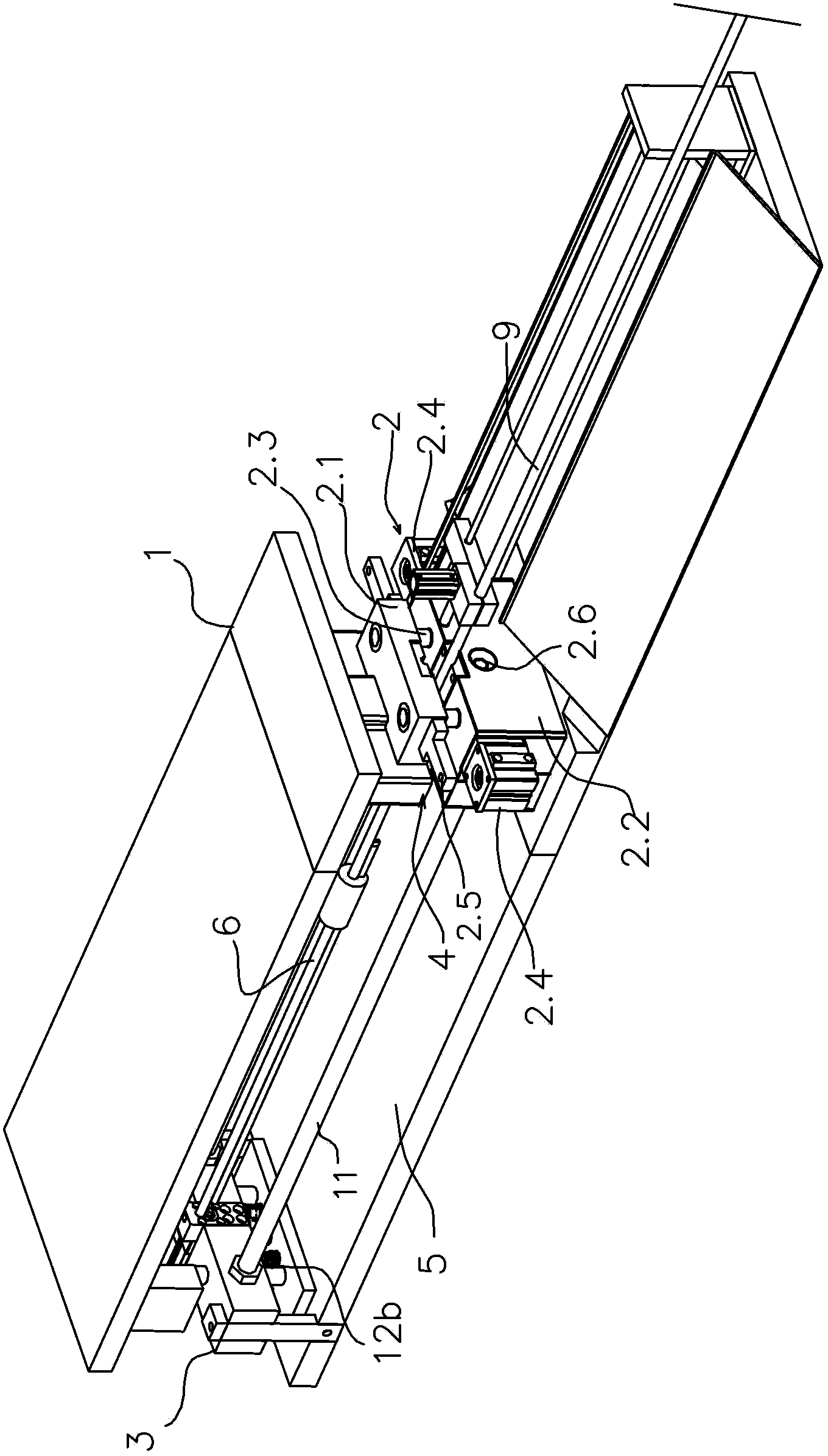
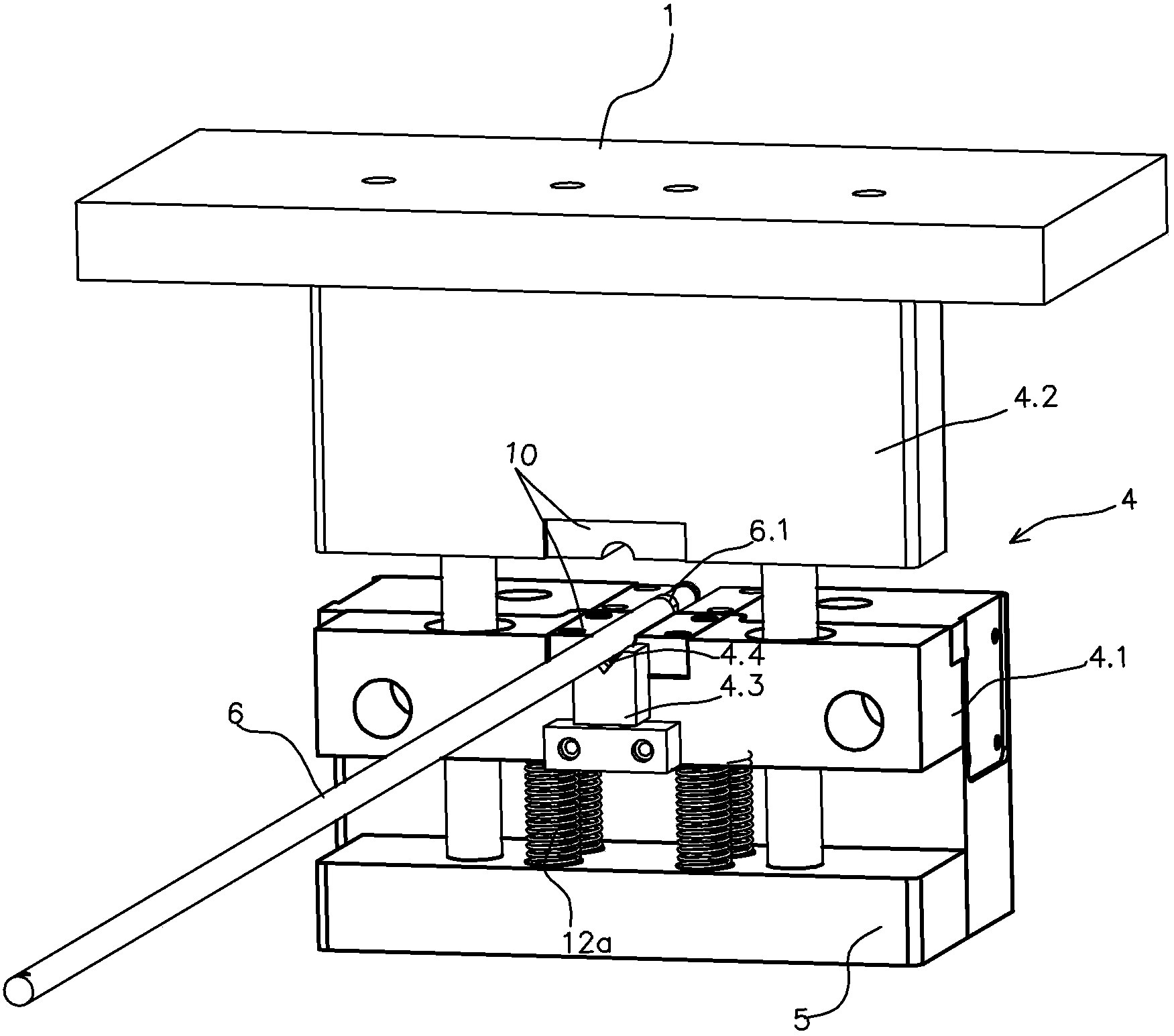
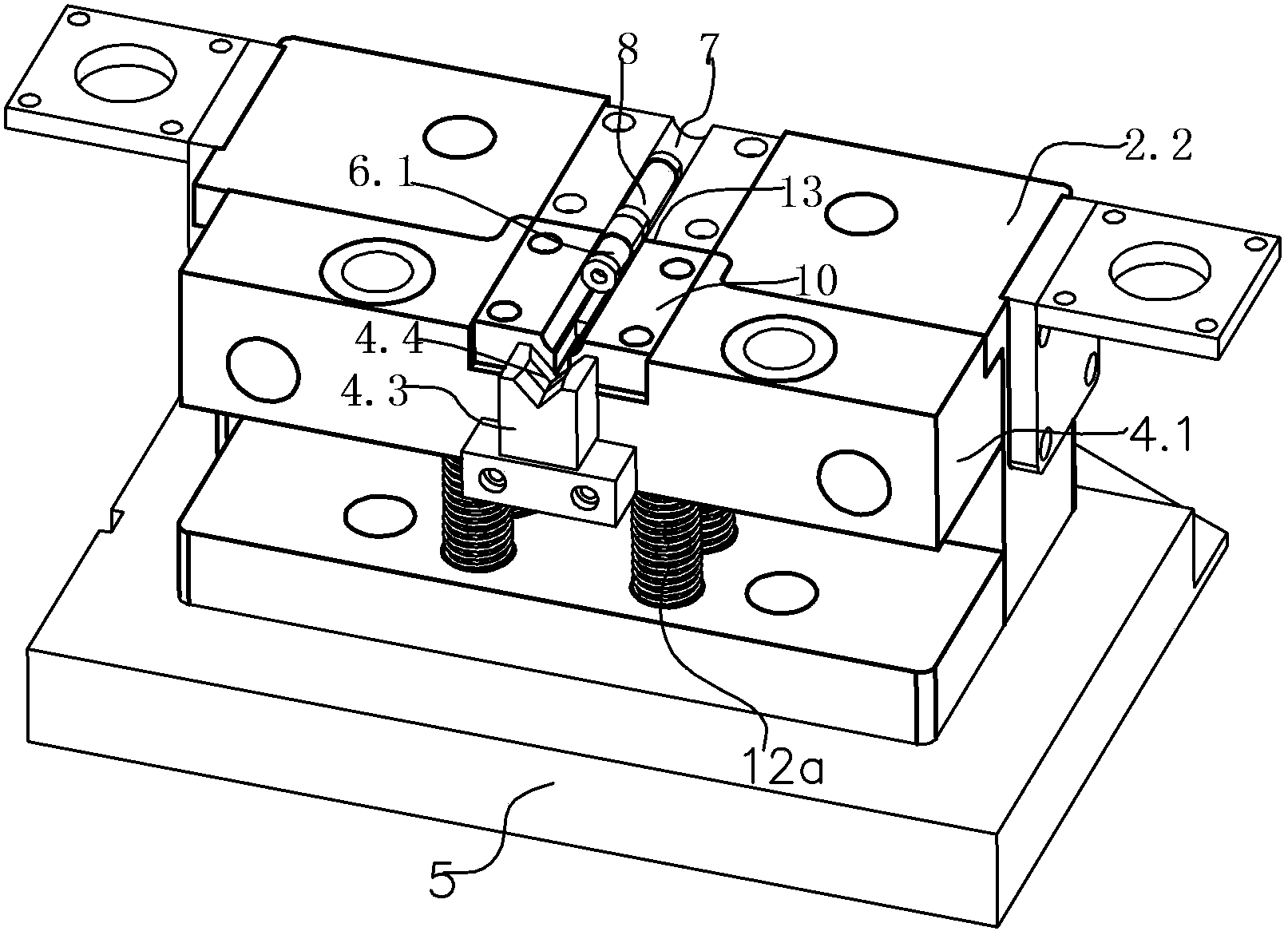
[0029] Such as Figure 1-3 As shown, a high-precision pipe cutting device includes main components such as an upper mold fixing plate 1, a clamping mold base 2, a mandrel fixing frame 3, and a pipe cutting mechanism 4; wherein:

[0030] The upper mold fixed plate 1 is connected with a stamping device, and the upper mold fixed plate 1 can be pressed down and raised rapidly under the action of the stamping device.

[0031] A clamping mold base 2 is fixed on the base 5, and the clamping mold base 2 includes two parts, an upper clamping mold 2.1 and a lower clamping mold 2.2, which can be separated. Two guide pillars 2.3 are installed on the lower clamping mold 2.2. 2.1 is sleeved on the guide post 2.3 and can slide up and down along the guide post 2.3. In order to realize the clutch between the upper clamping die 2.1 and the lower clamping die ...


PUM


Abstract

A pipe cutting device comprises an upper mold fixing plate, a mold clamping seat, a core bar fixing frame, a pipe cutting mechanism, and the like. Through a core bar with a magnetic core head and a liner cutter mold embedded with a magnet, pipe openings can be cut to be round and tidy, in addition, the upper mold fixing frame is connected with a stamping device, the stamping technology replaces the traditional saw cutting technology, burrs can be effectively reduced, flatness of cut pipe openings of machined pipe fittings is improved, and the overall structure is reasonable and practical.

Description

technical field [0001] The invention relates to the technical field of cutting equipment, in particular to a high-precision pipe cutting device for cutting small-diameter pipe fittings. Background technique [0002] In general pipe fitting processing operations, in order to meet the needs of pipe fitting design, in addition to bending processing steps such as bending pipes on specific parts of the pipe fittings, it also includes cutting steps based on the length of the pipe fitting design. The cutting step can be combined with the pipe bending step to continue, and the cutting step can also be performed after the pipe is bent. [0003] In order to carry out the above-mentioned pipe cutting steps, most of the current methods are to use a set of pipe cutting devices to perform pipe cutting operations. The pipe cutting devices mainly include a pipe clamping assembly and a set of pipe cutting assemblies driven by a driving device. The pipe cutting assembly described above cuts ...

Claims


Application Information

Patent Timeline
IPC IPC(8): B23D21/00
Inventor 陆志伟陈军
Owner ZHEJIANG MOTORBACS TECH
Why Eureka
Try Eureka