In-grinding coordinate automatic compensation method based on end face cylindrical grinder

A cylindrical grinding machine, automatic compensation technology, applied in the direction of grinding machine parts, grinding/polishing equipment, workpiece feed movement control, etc., can solve the problem of large compensation amount

Active Publication Date: 2014-03-26
SHANGHAI MACHINE TOOL WORK
View PDF5 Cites 14 Cited by
  • Summary
  • Abstract
  • Description
  • Claims
  • Application Information

AI Technical Summary

Problems solved by technology

Moreover, as the grinding wheel wears out, the amount of compensation will become larger

Method used

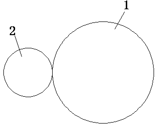
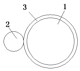
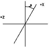

Image

  • In-grinding coordinate automatic compensation method based on end face cylindrical grinder
  • In-grinding coordinate automatic compensation method based on end face cylindrical grinder
  • In-grinding coordinate automatic compensation method based on end face cylindrical grinder

Examples


Embodiment Construction

[0015] An automatic compensation method based on the coordinates in the grinding of the end face cylindrical grinder:

[0016] First of all, for the convenience of grinding in workpiece grinding, it is necessary to establish a workpiece coordinate system. In this coordinate system, we make the zero point of the workpiece consistent with the zero point of the workpiece coordinate system. After that, a new coordinate system needs to be re-established. Therefore, each time the coordinate system is established, the difference between the target coordinates and the machine coordinates is stored in the macro variable. Every time the machine is turned on, the coordinate system is established again according to the stored macro variable. . For example: the diameter of a workpiece is 100mm. At this time, the mechanical coordinates may be at any position, which we cannot control. However, a workpiece coordinate system can be established by using macro variables. In this coordinate syste...


PUM


Abstract

The invention relates to an in-grinding coordinate automatic compensation method based on an end face cylindrical grinder. The method comprises the steps that when a coordinate system is established each time, difference values of target coordinates and mechanical coordinates are stored in a macro-variable, digital-controlled macro-variable memory coordinates are used for compensation amount and grinding wheel conditioning compensation amount, programs are called for computing coordinate values again each time a machine is started, and workpiece coordinates are automatically compensated; when coordinates are set manually, difference values before and after coordinate compensation are stored in the macro-variable, adding with grinding wheel diamond coordinates is carried out, and new diamond coordinates and grinding wheel frame safe position coordinates are computed; a measuring instrument is used for sending a signal to a CNC in a first gear for grinding multi-gear workpieces, a jumping-switching instruction is used in a program, accumulating is carried out on the measuring instrument compensation value each time, and the measuring instrument compensation values are stored in the macro-variable and are marked as measuring instrument accumulating compensation values; and before next grinding, the measuring instrument accumulating compensation values are subtracted from the first-time-established coordinate values. According to the method, errors caused by lathe repeated locating accuracy and grinding wheel loss can be automatically compensated during a grinding process.

Description

technical field [0001] The invention relates to an automatic method for adjusting workpiece coordinates in workpiece grinding and grinding wheel dressing of an end surface cylindrical grinder. Background technique [0002] At present, on a CNC grinding machine without a grating ruler, due to the repeated positioning accuracy of the machine tool itself, the loss of the grinding wheel in the grinding wheel dressing and other reasons often cause the final size of the workpiece to be out of tolerance after grinding. Many machines can only be compensated by the operator's grinding experience manually entered every time they grind. This compensation method requires the operator to measure the size of the workpiece after each grinding to calculate the amount to be compensated. Also, as the grinding wheel wears out, the amount of compensation will become larger. Contents of the invention [0003] The purpose of the present invention is to overcome the shortcomings of the current...

Claims


Application Information

Patent Timeline
Patent Type & Authority Applications(China)
IPC IPC(8): B24B49/02
CPCB24B49/00
Inventor 高毅陈禹周小兵卢典庆
Owner SHANGHAI MACHINE TOOL WORK
Why Eureka
Try Eureka