Direction changing device and transferring device

A direction conversion, horizontal direction technology, applied in conveyors, mechanical conveyors, transportation and packaging, etc., can solve problems such as difficulty in adjustment, and achieve the effect of miniaturization and improved safety

Active Publication Date: 2014-03-26
MEGALITE IND
View PDF5 Cites 5 Cited by
  • Summary
  • Abstract
  • Description
  • Claims
  • Application Information

AI Technical Summary

Problems solved by technology

However, there is a problem that when the shape of the engine is changed or the number of production units is changed along with the product update of the automobile, the assembly stroke

Method used


Image

  • Direction changing device and transferring device
  • Direction changing device and transferring device
  • Direction changing device and transferring device

Examples


Embodiment Construction

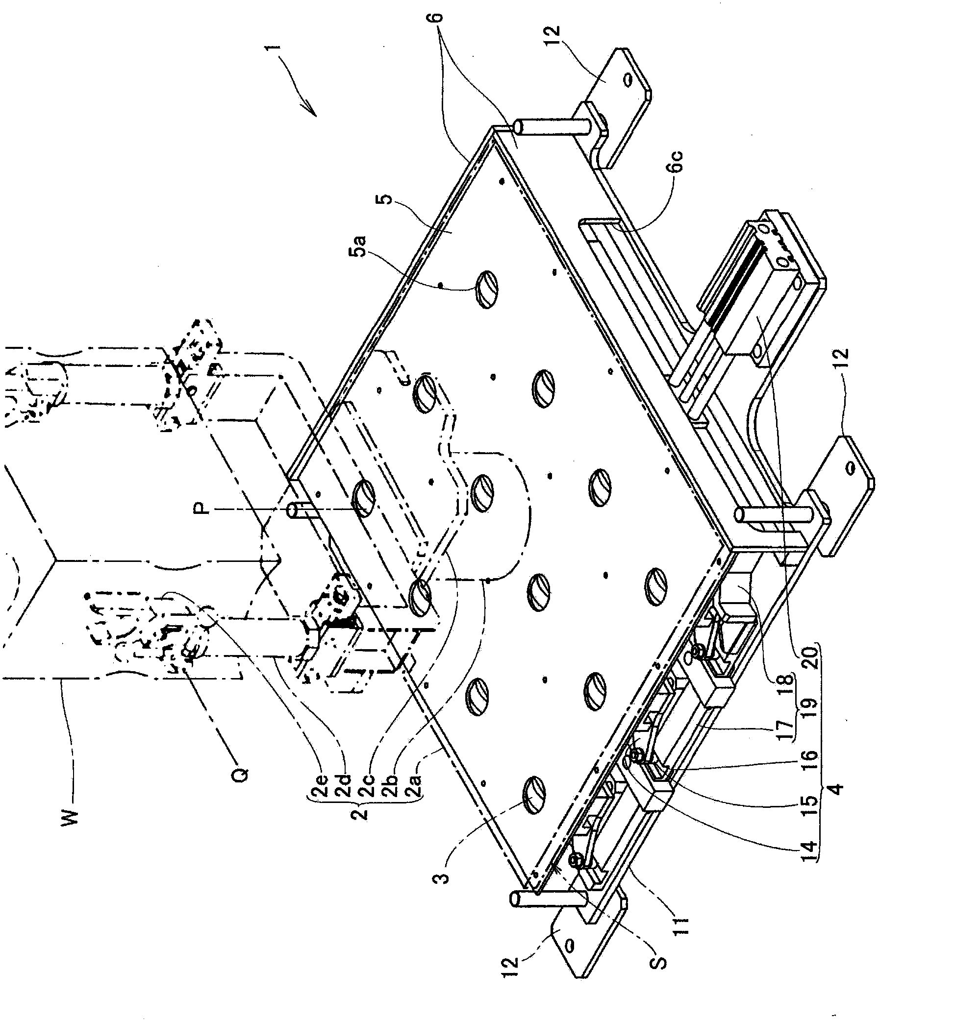
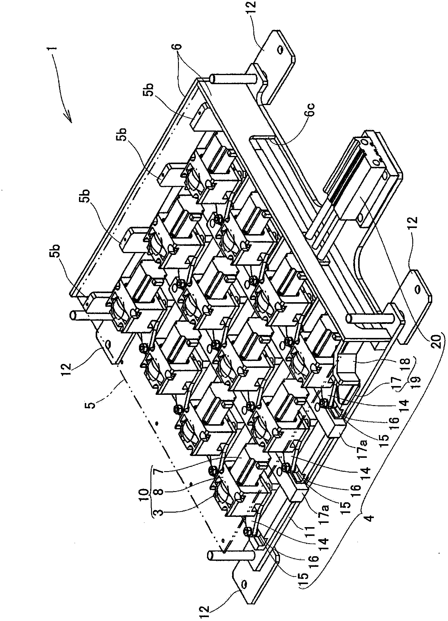
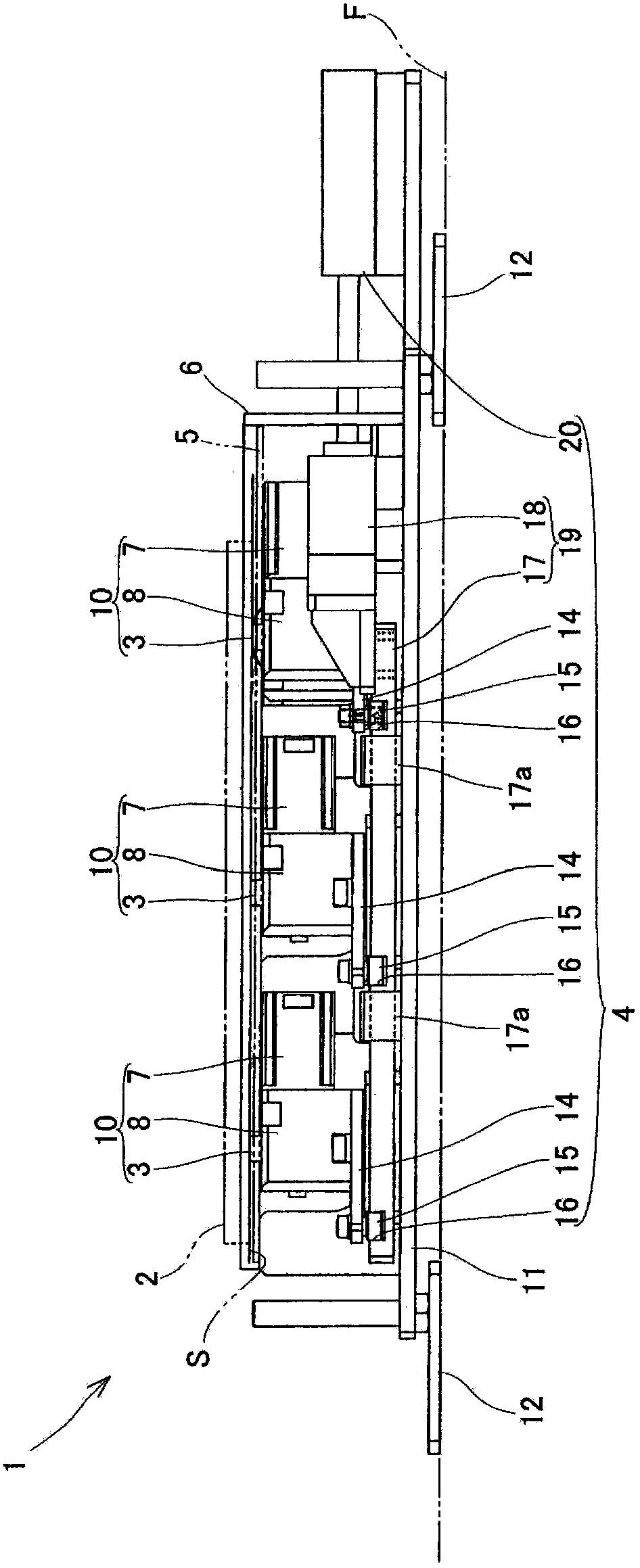
[0051] Figure 1 to Figure 7 It shows the direction changing device 1 according to the first embodiment of the present invention that rotates the roller unit by 90° by using an air cylinder to move the cam follower provided on the turning mechanism back and forth when turning the roller unit. Structure diagram. Such as figure 1 As shown, the direction changing device 1 of the present invention includes: a plurality of rollers 3 arranged along a two-dimensional direction substantially parallel to the conveying surface S, and abutting against the lower surface of the pallet 2 (transported object) on which workpieces W such as engines are mounted. Surface; Rotary mechanism 4, makes the rotating shaft of each roller 3 rotate around the vertical axis simultaneously; The top surface cover 5 of plan view approximately square shape, is parallel with conveying surface and is formed with through-hole 5a at the position of described each roller 3; And guide plate 6. Installed on the s...


PUM


Abstract

The invention provides a direction changing device and a transferring device. The direction changing device and the transferring device can lower a transferring surface and change assembling lines easily. According to the direction changing device and the transferring device, driving motors (7, 7') are arranged on multiple idler wheels (3, 3', 3') abutting against the lower surface of an object to be transferred respectively to form an idler wheel unit (10), and rotating mechanisms (4, 4', 4') enabling rotating shafts (3a) of the idler wheels (3, 3', 3') to rotate around longitudinal axes together are further arranged.

Description

technical field [0001] The present invention relates to a direction changing device and a conveying device that are installed on the same floor as the conveyor belts that transport objects to be conveyed in one direction, and interposed between the conveyor belts to change the direction of the object to be conveyed. Background technique [0002] For example, on an assembly line where each part is distributed in line and assembled into a workpiece such as an engine, a conveyor belt is installed along each assembly station, and the pallet is conveyed by the conveyor belt while the workpiece is placed on a pallet-type jig , so that in each process, the operator performs processing and assembly operations on the workpiece. [0003] Figure 21 It is a figure which shows the whole structure of the conventional conveying apparatus 90. As shown in FIG. In this conveying device 90, the direction changing device 93 is interposed between the conveying belts 92 for conveying the pallet...

Claims


Application Information

Patent Timeline
IPC IPC(8): B65G35/00
Inventor 川澄诚
Owner MEGALITE IND
Why Eureka
Try Eureka