
Motor and control device for starting and power generation of internal combustion engine

A technology for control devices and internal combustion engines, which is applied in the direction of machines/engines, internal combustion piston engines, and electric motors for engines, etc. It can solve the problems of easily damaged electronic components on the vehicle, excitation current imbalance, and low battery voltage, etc., to reduce the strong magnetic field radiation effect

Pending Publication Date: 2022-07-12
SHENZHEN SENSOR TECH CO LTD
View PDF0 Cites 0 Cited by
  • Summary
  • Abstract
  • Description
  • Claims
  • Application Information

AI Technical Summary

Problems solved by technology

[0003] Existing starter motors are permanent magnet DC motors. When starting, the current is hundreds of amperes, which will radiate a strong magnetic field, which will seriously interfere with the surrounding crankshaft speed, camshaft position and other sensors, which will easily cause poor startup. Pulling down the battery voltage will seriously affect the operation of ECU and various electrical appliances; the generator is a three-phase AC motor, and when it is started and the engine speed changes rapidly, it is prone to excitation current imbalance and output high pulse voltage with an amplitude of up to 180 volts, which is the industry Standard "load dump mode", high pulse is easy to damage the electronic components on the car
[0004] In order to solve these problems of electromagnetic interference and high-voltage damage, it is necessary to improve the withstand voltage and anti-interference performance of the engine and the electronic components of the vehicle, which increases the product cost, and even so, it is still the most important factor causing vehicle electrical failures.

Method used


Image

  • Motor and control device for starting and power generation of internal combustion engine
  • Motor and control device for starting and power generation of internal combustion engine
  • Motor and control device for starting and power generation of internal combustion engine

Examples


Embodiment Construction

[0029] The preferred embodiments of the present invention will be described in detail below with reference to the accompanying drawings, so that the advantages and features of the present invention can be more easily understood by those skilled in the art, and the protection scope of the present invention can be more clearly defined. Obviously, the described embodiments are only some, but not all, embodiments of the present invention. Based on the embodiments of the present invention, all other embodiments obtained by those of ordinary skill in the art without creative work fall within the protection scope of the present invention.

[0030] The terms "comprising" and "having" and any variations thereof in the description and claims of the present invention and the above description of the drawings are intended to cover non-exclusive inclusions. The terms "first", "second" and the like in the description and claims of the present invention or the above drawings are used to dist...


PUM


Abstract

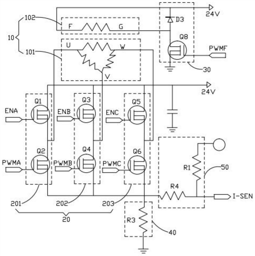
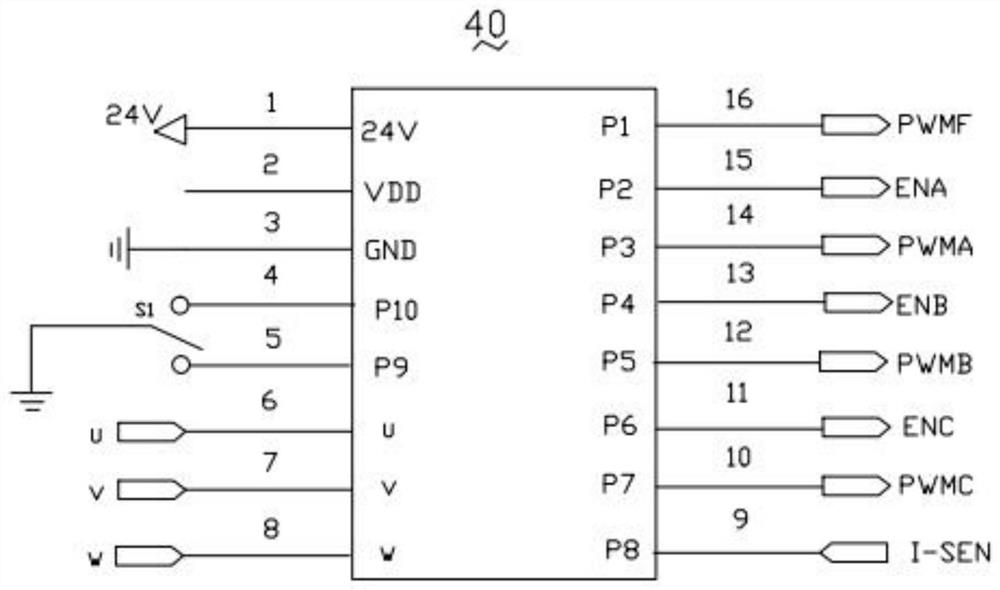
The invention discloses a motor and control device for starting and power generation of an internal combustion engine, the device comprises a motor main body, a three-phase inverter module, an exciting current input module and an MCU driver, control signal pins of the three-phase inverter module are all connected with the MCU driver, the three-phase inverter module is connected with the exciting current input module through the motor main body, and the exciting current input module is connected with the MCU driver. One end of the exciting current input module is connected with the MCU driver; wherein the three-phase inverter module comprises a first phase current group, a second phase current group and a third phase current group, and the motor main body comprises a rotor coil and a stator coil; one end of the first phase current group is connected with a first terminal of the stator coil, one end of the second phase current group is connected with a second terminal of the stator coil, one end of the third phase current group is connected with a third terminal of the stator coil, and a first end of the rotor coil is connected with the excitation current input module; the second end of the rotor coil is connected with the power supply. The cable has the advantages of electromagnetic interference resistance, voltage resistance and low product cost.

Description

technical field [0001] The present invention relates to the technical field of control circuits, in particular to a motor and a control device for starting and generating electricity of an internal combustion engine. Background technique [0002] Internal combustion engines are equipped with starter motors and generators, which work in different periods of time. When the internal combustion engine needs to be started, the key switch is connected to the power supply circuit of the starter motor, and the motor converts the electric energy of the battery into kinetic energy, which drives the crankshaft of the engine to rotate. When the speed reaches a certain speed, the ECU (control computer) of the engine recognizes the crankshaft speed. After the sensor signals such as camshaft position and camshaft position, it starts to control the fuel injection, the engine cylinder piston works to drive the crankshaft to rotate, the engine starts to complete, and the starter motor stops; ...

Claims


Application Information

Patent Timeline
IPC IPC(8): F02N11/08F02N11/04
CPCF02N11/0859F02N11/04F02N2011/0896Y02T10/40
Inventor 李纯钢袁春李建设梁旭东刘曲
Owner SHENZHEN SENSOR TECH CO LTD
Learn More