Continuous rigid frame bridge based on steel truss-concrete slab composite beam

A technology of concrete slabs and steel trusses, applied in truss bridges, bridges, bridge parts, etc., can solve the problems of low bearing capacity, single structural form, and difficult construction.

Inactive Publication Date: 2014-03-26
CHANGAN UNIV
View PDF8 Cites 16 Cited by
  • Summary
  • Abstract
  • Description
  • Claims
  • Application Information

AI Technical Summary

Problems solved by technology

[0005] The technical problem to be solved by the present invention is to provide a continuous rigid frame bridge based on steel truss-concrete slab composite beams, which has simple structure, reasonable design, convenient construction and excellent mechanical performance, and is easy to use. The effect is good, and it can effectively solve the problems existing in the existing continuous rigid frame bridges such as single structural form, low bearing capacity, and difficult construction

Method used


Image

  • Continuous rigid frame bridge based on steel truss-concrete slab composite beam
  • Continuous rigid frame bridge based on steel truss-concrete slab composite beam
  • Continuous rigid frame bridge based on steel truss-concrete slab composite beam

Examples


Embodiment 1

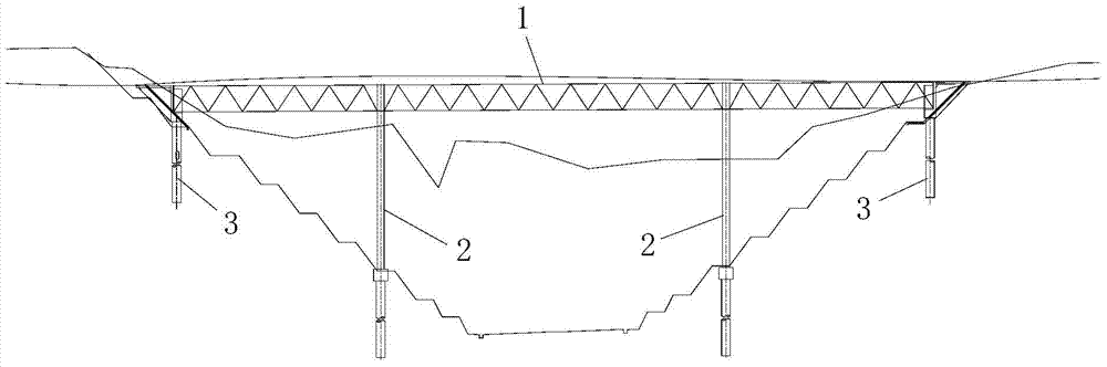
[0088] Such as figure 1 The shown continuous rigid frame bridge based on steel truss-concrete slab composite beams comprises a bridge substructure and a steel truss-concrete slab composite beam 1 supported on the bridge substructure, and the bridge substructure includes The bridge pier 2 and abutment 3 supported by the steel truss-concrete slab composite girder 1, both of which are concrete structures.

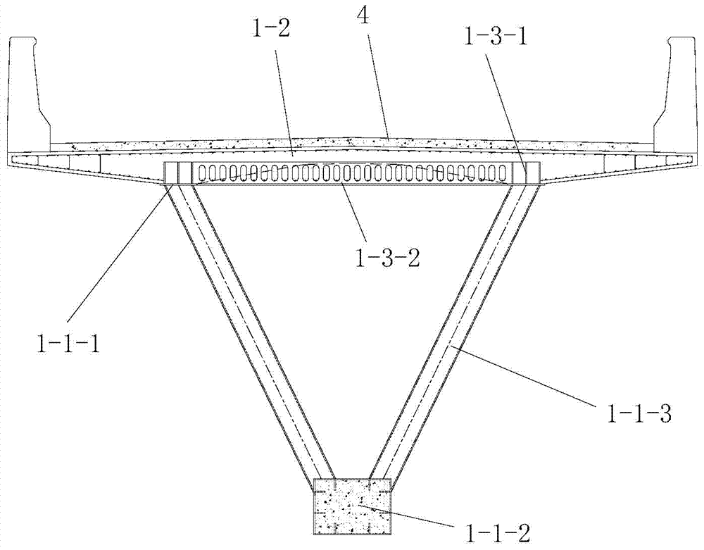
[0089] Such as Picture 1-1 , Figure 1-2 As shown, the steel truss-concrete slab composite girder 1 includes a steel truss arranged in the longitudinal bridge direction and a concrete bridge deck 1-2 arranged directly above the steel truss, and the concrete bridge deck 1-2 is in the form of a longitudinal bridge to layout. The steel truss includes one or more steel truss units 1-1 arranged in the direction of the longitudinal bridge, and a plurality of steel truss units 1-1 are arranged on the same horizontal plane from left to right in the direction of the transverse brid...

Embodiment 2

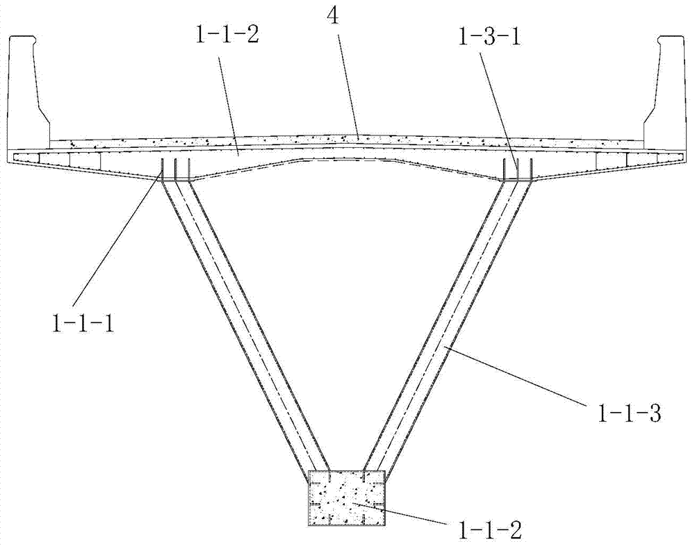
[0166] In this example, if Figure 4 As shown, the difference from Embodiment 1 is that the number of steel truss units 1 included in the steel truss is multiple, and the left and right adjacent steel truss units 1-1 in the lattice type upper chord structure share the same The upper chords 1-1-1 of the common type upper chords are common type upper chords, and the upper chords 1-1-1 in the lattice type upper chord structure are all common type upper chords except the shared type upper chords; The distance between two adjacent vertical perforated steel plates 1-3-1 in the upper chord is greater than the distance between the two adjacent vertical perforated steel plates 1-3-1 in the ordinary upper chord spacing between.

[0167] In this embodiment, the left and right adjacent lower chords 1-1-2 of the two steel truss units 1-1 are two left and right adjacent lower chords 1-1-2 arranged on the same plane, and the lower chord transverse connection system 1-1-5 is arranged on the...


PUM

PropertyMeasurementUnit
thicknessaaaaaaaaaa
thicknessaaaaaaaaaa
heightaaaaaaaaaa

Abstract

The invention discloses a continuous rigid frame bridge based on a steel truss-concrete slab composite beam. The continuous rigid frame bridge comprises a bridge substructure and the steel truss-concrete slab composite beam supported by the bridge substructure. The steel truss-concrete slab composite beam comprises a steel truss and a concrete bridge deck which is laid over the steel truss. The steel truss comprises one or more steel truss units; each steel truss unit is an inverted-triangle truss girder, wherein the inverted-triangle truss girder is composed of two upper chords, a lower chord, a left line of diagonal web members and a right line of diagonal web members, each upper chord comprises a first horizontal steel plate and a plurality of first vertical perforated steel plates evenly laid on the first horizontal steel plate, an upper chord transverse connecting system connected between the two upper chords comprises a plurality of upper chord transverse connecting pieces, and each upper chord transverse connecting piece comprises a second horizontal steel plate and a plurality of second vertical perforated steel plates evenly laid on the second horizontal steel plate. The continuous rigid frame bridge is simple in structure, reasonable in design, convenient to construct, good in stress performance, good in using effect and capable of effectively solving various problems existing in an existing continuous rigid frame bridge.

Description

technical field [0001] The invention relates to a continuous rigid frame bridge, in particular to a continuous rigid frame bridge based on a steel truss-concrete plate composite beam. Background technique [0002] At present, the continuous rigid frame bridge is the mainstream bridge structure in my country, and the prestressed concrete girder combined with the reinforced concrete pier structure is the main form. But the prestressed concrete continuous rigid frame bridge has a high proportion of dead load to the total load, low bearing capacity, single structural form, and low recycling rate. With the further increase of the span of the bridge, the proportion of the internal force of the live load decreases, and the difficulty of construction increases, which is contrary to the development trend of long-span and light-weight bridges. [0003] In the case of the same span and the same structural system, if the continuous rigid frame bridge combined with concrete filled steel...

Claims


Application Information

Patent Timeline
Patent Type & Authority Applications(China)
IPC IPC(8): E01D12/00E01D6/00E01D19/00E01D19/02
Inventor 刘永健袁卓亚程高龙刚王旭刘鸽
Owner CHANGAN UNIV
Why Eureka
Try Eureka