

Standard Bailey truss assembling type jacking formwork system
A beret, standard technology, applied in the field of standard beret prefabricated jacking formwork system, to achieve the effect of protecting safety, light weight, ensuring safety and quality
- Summary
- Abstract
- Description
- Claims
- Application Information
AI Technical Summary
Problems solved by technology
Method used
Image

Examples
Embodiment 1
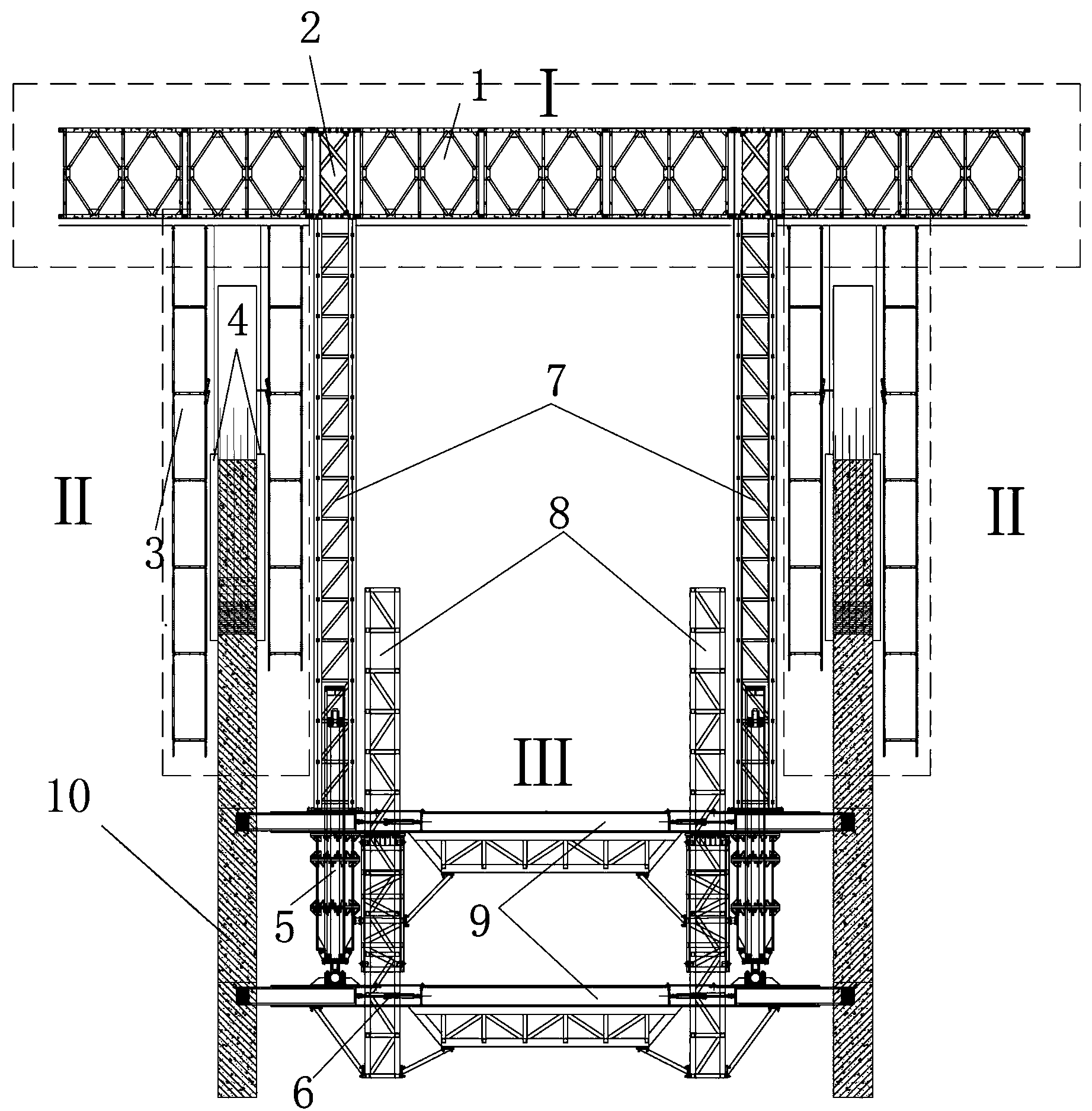
[0067] Such as figure 1 , 2 As shown in , 3 and 10, a standard Bailey frame assembled jacking formwork system is mainly composed of truss platform system I, suspension system II and dynamic support jacking system III, and the dynamic support jacking system III It is fixedly supported on the core tube wall 10, and its upper part is connected with the truss platform system I through the lattice support steel column 7, and the suspension system II is suspended on the truss platform system I;
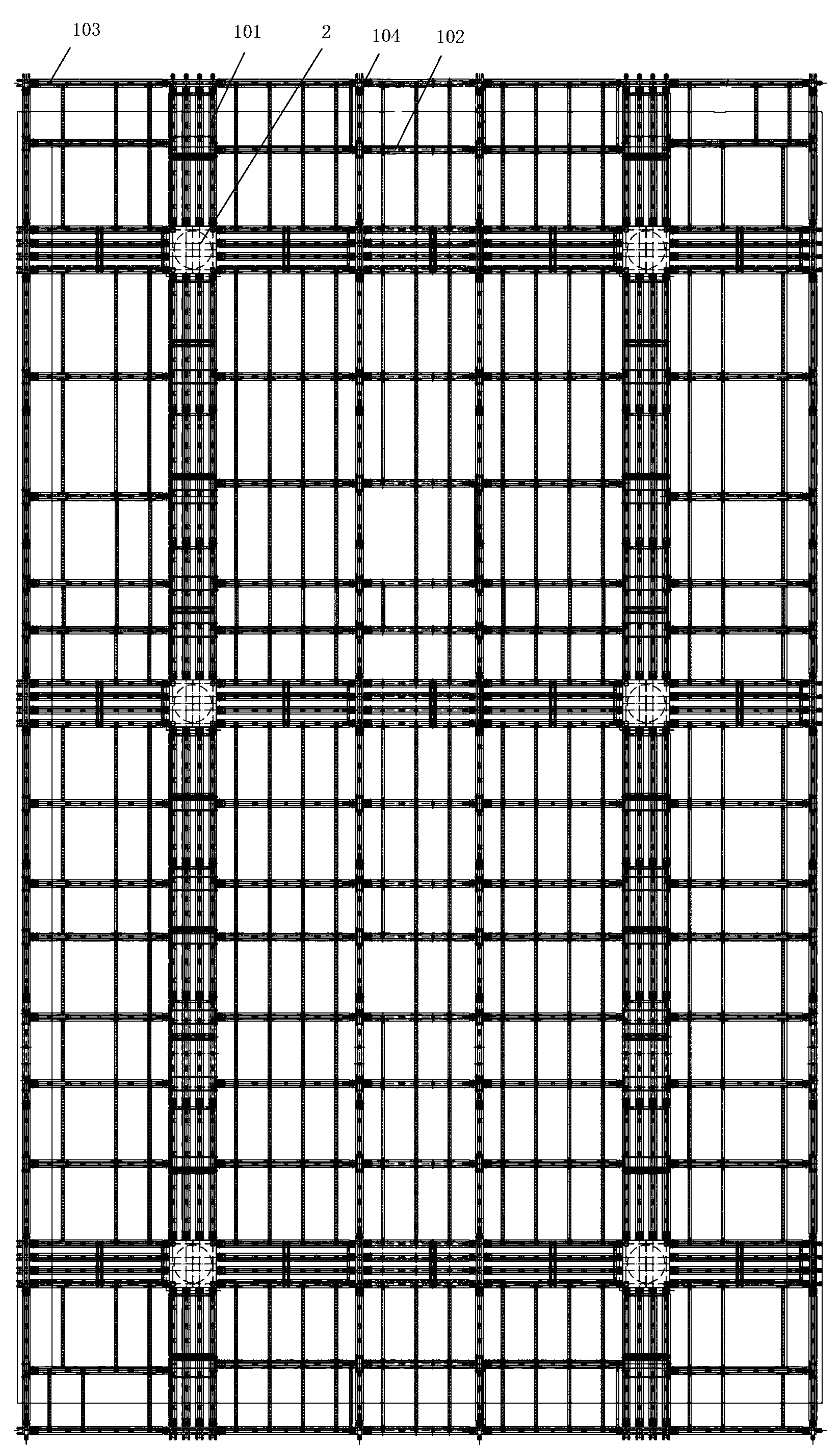
[0068] The truss platform system I is mainly composed of several standard Bailey frames 1, which are connected and assembled into primary and secondary trusses 101, 102; Connected to form a main frame, connect a rectangular peripheral frame 103 on the periphery of the main frame through the standard Bailey frame 1, and connect secondary The truss 102, the main truss 101, the secondary truss 102 and the peripheral frame 103 together constitute a truss platform system I with a palace-shaped...
Embodiment 2
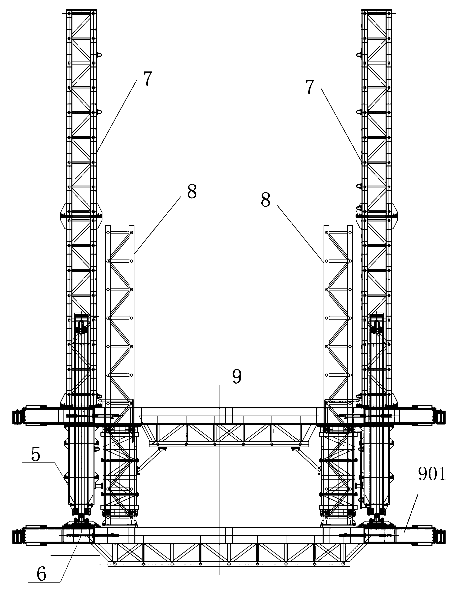
[0083] Such as figure 1 , 3 As shown, in the dynamic support jacking system III, the upper and lower box girders 9 are connected to each other through a pair of jacking cylinders 5, and a pair of jacking cylinders 5 are symmetrically distributed along the center line of the box girder 9; the jacking cylinders 5 The upper and lower layers of box girder 9 are connected by flange bolts, and the flange and box girder 9 are connected by welding. The jacking cylinder 5 is equipped with a steel cylinder (the steel cylinder protects the jacking cylinder 5), and the steel cylinder and the upper layer The box girder 9 is welded and connected; the upper box girder 9 is fixedly connected with two lattice support steel columns 7, and the two lattice support steel columns 7 are respectively located directly above a pair of jacking cylinders 5; the box girder 9 The two ends of each are connected with a corbel 901 (the corbel 901 is inserted into a preset hole on the wall 10 of the core tube...
Embodiment 3
[0089] Such as Figure 10-14 As shown, the protective operation frame 3 includes a plurality of single-layer hangers connected from top to bottom, and the uppermost single-layer hanger is hung on the lower chord of the standard Bailey frame 1; the single-layer hanger The frame includes four vertical rods 301, two cross rods 303, a scaffold board 304, a facade protection net 305 and an inner flap 306, and the lower end of each vertical rod 301 is provided with a vertical rod connector 302, and the vertical rod The upper end of the connector 302 is telescopically fixedly connected to the lower end of the vertical rod 301; the four vertical rods 301 are in pairs, and each group of two vertical rods 301 is fixedly connected by a cross bar 303, and the two ends of the cross rod 303 The middle parts of the pole connectors 302 at the lower ends of the two poles 301 are respectively detachably and fixedly connected, and the two poles 301 in each group are vertically parallel and symme...
PUM
 Abstract
Description
Claims
Application Information