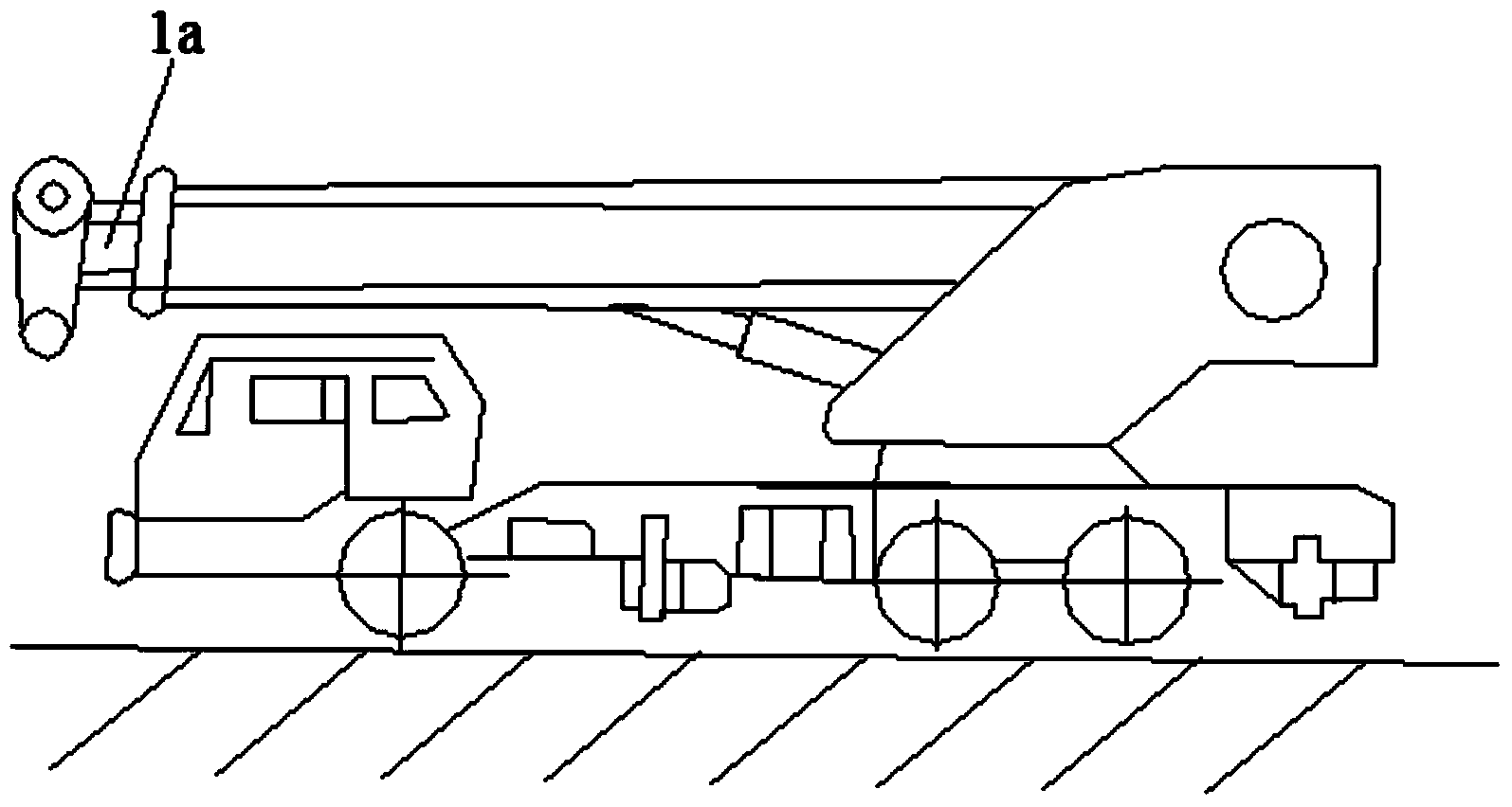
However, during the running of the truck crane, when the truck crane brakes suddenly, the rod cavity of the telescopic oil cylinder 3b is impacted instantaneously. Although the one-way valve 61b has a certain resistance or damping effect, it is not enough to prevent the
active movement of the telescopic oil cylinder 3b. The rod chamber returns oil, at this time the
piston rod of the
telescopic cylinder 3b will still drive the boom 1a forward for a certain distance due to
inertia, which needs to be avoided as much as possible during the driving of the truck crane
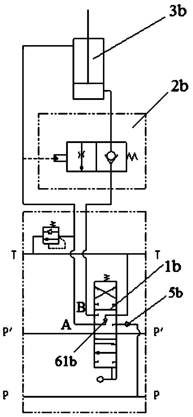
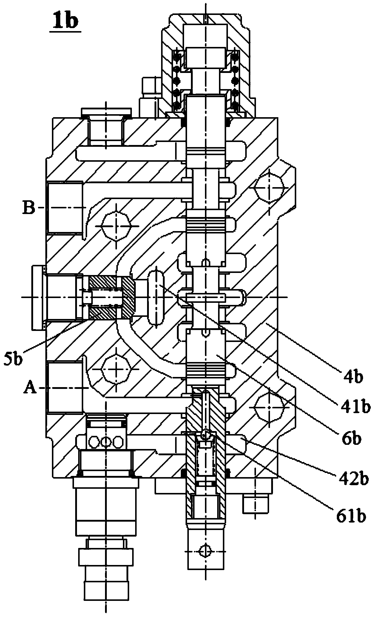
[0006] In addition, the Chinese utility model patent CN202322045U also discloses another structural scheme of the reversing valve. In the structure of the reversing valve, figure 2 and image 3 The one-way valve 61b in the valve is replaced by a damping hole. In this way, when the first working oil port A forms a pressure shock, the damping hole in the valve core forms a damping, thereby slowing down the oil return speed of the rod cavity of the
telescopic cylinder 3b. The first working The oil port A achieves a certain degree of pressure maintenance, but the damping hole is not enough to prevent the rod chamber of the telescopic oil cylinder 3b from returning oil, and the
piston rod of the telescopic oil cylinder 3b will still drive the boom 1a to extend forward for a certain distance due to
inertiaMoreover, considering that the rod chamber of telescopic cylinder 3b needs to realize pressure relief during the normal operation of the truck crane, generally the flow
diameter of the damping hole in the valve core 6b is relatively large to ensure that after the valve core 6b returns to the
neutral position, the first The working oil port A will quickly release the pressure, so that the balance valve 2b will also be closed quickly, and the telescopic cylinder 3b will also stop moving immediately, but the relatively large flow
diameter of the damping hole will inevitably weaken the damping effect of the damping hole. The rod cavity of the telescopic oil cylinder 3b is subject to pressure shock due to sudden braking during the driving of the truck crane, which will certainly not be able to effectively hinder the oil return from the rod cavity of the telescopic oil cylinder 3b, and the
piston rod of the telescopic oil cylinder 3b will move forward. extended, causing boom 1a to extend a relatively
large distance forward
On the other hand, even if the flow
diameter of the damping hole is reduced, as mentioned above, not only the suspension arm 1a cannot be completely eliminated when the truck crane protrudes forward due to sudden braking, etc., but also will occur during the normal operation of the truck crane This results in a
delay in the closing of the balance valve 2b, which affects the normal operation of the truck crane. Specifically, when the valve core 6b returns to the
neutral position, the first working oil port A will maintain a relatively
high pressure due to the relatively small flow diameter of the damping hole. , which will cause the first working oil port A to release pressure for a long time when the boom is normally retracted, the balance valve will be closed for a
delay, and the telescopic boom will continue to retract improperly, thus affecting the normal operation of the truck crane
[0007] In addition to the reversing valve structure disclosed in the utility model patent CN202322045U, Figure 4 and Figure 5 It shows a traditional reversing valve commonly used in the prior art. The neutral function of this traditional reversing valve can keep the pressure of the first working oil port and the second working oil port, which is not suitable for making the reversing valve One of the corresponding working oil ports connected to the hydraulic actuators is quickly relieved during normal operation (such as the first working oil port A connected to the rod cavity of the telescopic cylinder), and at the same time when needed (such as the truck crane Sudden braking during driving) can also make the above-mentioned corresponding working oil ports of the reversing valve maintain pressure relatively reliably
Figure 4 and Figure 5 The neutral function of the traditional reversing valve shown always makes the residual high
oil pressure in the corresponding working oil port connected to the hydraulic actuator, which will cause the above-mentioned balance valve 2b to fail to close in time when the hydraulic actuator is working normally. Affect the normal work of hydraulic actuators
Also, as mentioned above, figure 2 and image 3 The reversing valve with the
back pressure or
damping function in the middle function shown in will make the
residual oil pressure of one of the corresponding working oil ports connected to the hydraulic actuator of the reversing valve unable to release pressure in a short time, It affects the normal operation of the hydraulic actuators, and it cannot effectively solve the problems caused by the hydraulic actuators (such as the above-mentioned telescopic cylinder 3b) being subjected to pressure shocks (such as the
piston rod of the telescopic cylinder 3b stretching out for a period of time due to the
inertia of the boom) distance)
[0008] In view of the defects of the above-mentioned prior art, that is, the existing reversing valves are difficult to meet the requirement that only low oil pressure or no pressure is allowed to remain in the corresponding working oil port connected to the hydraulic actuator after the reversing valve returns to the
neutral position, and It can form a high-pressure specific working condition in the corresponding working oil pressure when the hydraulic actuator is impacted by pressure, so it is necessary to provide a new type of reversing valve

