Brake pads for high-speed trains and rail transit vehicles
A technology for rail transit vehicles and high-speed trains. It is applied in the braking field of high-speed trains and rail transit vehicles. It can solve problems such as unreasonable friction block shapes, friction block damage and heat dissipation, and troublesome replacement, so as to achieve simple processing and improve work efficiency. , The effect of convenient installation and disassembly
- Summary
- Abstract
- Description
- Claims
- Application Information
AI Technical Summary
Problems solved by technology
Method used
Image
Examples
specific Embodiment approach 1
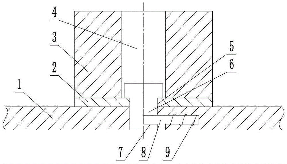
[0035] Specific examples of the present invention are attached figure 1 As shown, the brake pads for high-speed trains and rail transit vehicles include a steel base plate 1, a lining plate 2 and a friction block 3; it is characterized in that the center of the friction block 3 is processed with a central through hole 4 of the friction block; the friction block 3 and the lining plate 2 After welding or sintering under pressure; the steel bottom plate 1 is processed with a plurality of concentric through holes 5 on circular arcs with different radii; The through hole 5 of the base plate 1 is equipped with a bolt 8 and a spring 9; one side of the fastening nail 6 is processed with a pin hole 7; Hole 5, latch 8 is inserted in pin hole 7 and is fixed; Friction block 3 is oval, isosceles trapezoid, triangular triangular shape after cutting off, bicycle seat shape and other shapes.
specific Embodiment approach 2
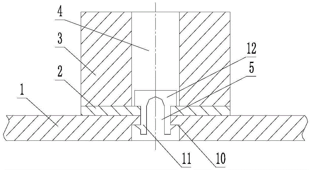
[0036] Specific examples of the present invention are attached figure 2As shown, it includes a steel base plate 1, a lining plate 2 and a friction block 3; it is characterized in that the center of the friction block 3 is processed with a central through hole 4 of the friction block; the friction block 3 and the lining plate 2 are welded or pressure sintered as one; The steel bottom plate 1 is processed with a plurality of concentric through holes 5 on circular arcs with different radii, and the lining plate 2 is processed with through holes 5 of the same specification as the steel bottom plate 1; Counterbore 10 is processed; one end of the split self-locking buckle 12 is a round table, and the other end is split, and an outward split self-locking buckle protrusion 11 is processed at the split end; the split self-locking buckle The split-type self-locking buckle protrusion 11 of the buckle 12 is inserted downward into the through-hole 4 in the center of the friction block, an...
specific Embodiment approach 3
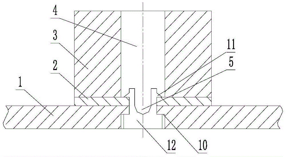
[0037] Specific examples of the present invention are attached image 3 As shown, it includes a steel base plate 1, a lining plate 2 and a friction block 3; it is characterized in that the center of the friction block 3 is processed with a central through hole 4 of the friction block; the friction block 3 and the lining plate 2 are welded or pressure sintered as one; The steel bottom plate 1 is processed with a plurality of concentric through holes 5 on circular arcs with different radii, and the lining plate 2 is processed with through holes 5 of the same specification as the steel bottom plate 1; Counterbore 10 is processed; one end of the split self-locking buckle 12 is a round table, and the other end is split, and an outward split self-locking buckle protrusion 11 is processed at the split end; the split self-locking buckle The split-type self-locking buckle protrusion 11 of the buckle 12 passes upwards through the through hole 5 of the lining plate 2 and the steel base p...
PUM
 Abstract
Description
Claims
Application Information
 - R&D
- Intellectual Property
- Life Sciences
- Materials
- Tech Scout
- Unparalleled Data Quality
- Higher Quality Content
- 60% Fewer Hallucinations
Browse by: Latest US Patents, China's latest patents, Technical Efficacy Thesaurus, Application Domain, Technology Topic, Popular Technical Reports.
© 2025 PatSnap. All rights reserved.Legal|Privacy policy|Modern Slavery Act Transparency Statement|Sitemap|About US| Contact US: help@patsnap.com


