
Flat phased-array antenna transmit-receive assembly integrated packaging tube shell

A technology for phased array antennas and transceiver components, applied to antenna components, antenna supports/mounting devices, antennas, etc., can solve problems such as complex assembly process, difficult positioning, and harsh welding quality of RF connectors, and reduce manufacturing costs. cost, and the effect of improving reworkability

Active Publication Date: 2021-06-22
10TH RES INST OF CETC
View PDF6 Cites 4 Cited by
  • Summary
  • Abstract
  • Description
  • Claims
  • Application Information

AI Technical Summary

Problems solved by technology

When the existing transceiver components composed of active chips, circuit boards, connectors, metal shells and cover plates fail, due to the complicated assembly process and the variety of devices used, it is necessary to gradually check the performance problems of each component and structural part itself The connection problem when assembling with each other, the problem location is difficult, and the repair time is long
However, most of the existing transceiver components use an integrated solution that encapsulates active chips, circuit boards, connectors and other components in a metal case. This solution must use radio frequency connectors to realize the signal interconnection between the transceiver components and the antenna.
Due to the extensive use of RF connectors, it not only pushes up the manufacturing cost of transceiver components, but also puts forward extremely strict requirements on the welding quality of RF connectors, which increases the difficulty of assembly and repair of transceiver components

Method used


Image

  • Flat phased-array antenna transmit-receive assembly integrated packaging tube shell
  • Flat phased-array antenna transmit-receive assembly integrated packaging tube shell
  • Flat phased-array antenna transmit-receive assembly integrated packaging tube shell

Examples


Embodiment Construction

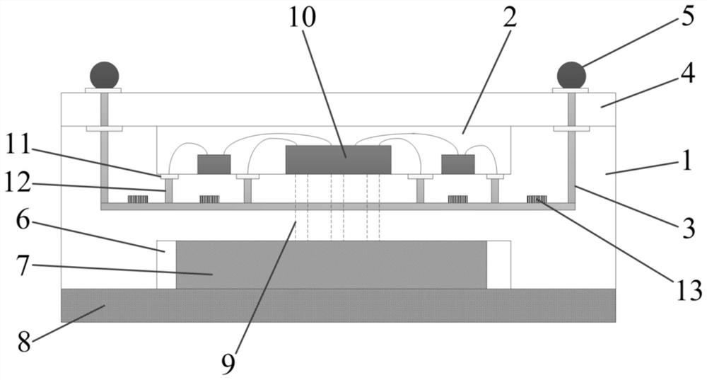
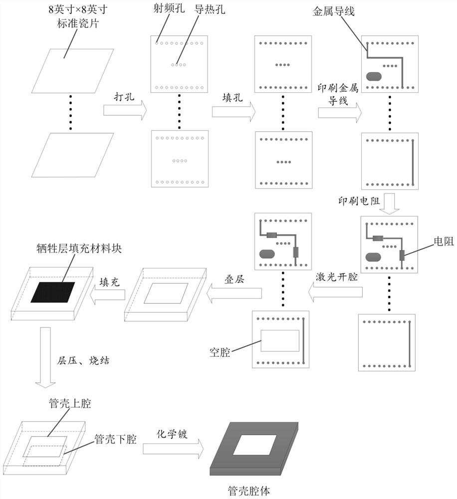
[0018] refer to figure 1 , figure 2. In the embodiment described below, a planar phased array antenna transceiver assembly is integrated into a package package, which has a rectangular package cavity 1 encapsulated by a package cover 4 and a package heat sink fixed at the bottom 8. The shell cavity 1 is divided into the upper shell cavity 2 and the lower shell cavity 6 by the intermediate medium layer, and the middle part of the stepped surface of the intermediate medium layer is provided with a radio frequency chip 10 as a transceiver component and is connected to the radio frequency chip 10 through a bonding gold wire, And the chip capacitors distributed symmetrically on both sides of the radio frequency chip 10, the radio frequency chip 10 and the chip capacitor are connected to the connection pad 11 through the bonding gold wire, and connected to the radio frequency transmission hole 12 embedded in the intermediate medium, and the radio frequency chip 10 passes through ...


PUM


Abstract

The invention discloses an integrated packaging tube shell for a transmitting-receiving assembly of a flat phased-array antenna, and aims to solve the problem of high-efficiency heat dissipation of the transmitting-receiving assembly in a narrow space during working. According to the technical scheme, a tube shell cavity is divided into a tube shell upper cavity and a tube shell lower cavity by a middle dielectric layer, chip capacitors are distributed on the two sides of a radio frequency chip, and meanwhile the radio frequency chip is communicated with a phase change material layer through array heat dissipation through holes penetrating through the middle dielectric layer; the radio frequency chip realizes signal transmission with an antenna network through a printed metal wire which is distributed along a dielectric layer on the inner wall of the tube shell and extends to the bottom of the embedded cavity, a printed resistor on the metal wire and linear array solder balls which are arranged on two sides of an upper cover of the interconnected tube shell; heat exchange between the radio frequency chip and the external environment is achieved through heat dissipation through holes arranged in the middle medium in an array mode, a phase change material layer communicated with the heat dissipation through holes and filled in a lower cavity of the tube shell and a tube shell heat sink fixedly connected to the bottom end of the tube shell, and the efficient heat dissipation function of the radio frequency chip in the integrated airtight packaging structure in the working process is completed.

Description

technical field [0001] The invention relates to a flat-panel phased array antenna mainly used for communication and navigation functions in the aerospace field, and in particular to a structural part that can be used as a carrier for devices such as transceiver components, radio frequency chips, etc., and can also be used as a function of interconnecting devices and antenna networks The antenna transceiver assembly of the component is packaged in a package. Background technique [0002] The phased array antenna can perform beamforming configuration on N antenna elements, and electronically control the amplitude and phase excitation of each individual antenna element in the phased array antenna intelligently to generate a beam pointing in the desired direction , when the physical structure is fixed, beamforming and beam scanning can be performed quickly and without inertia. It has excellent performance in the beam-forming design of the front end of the phased array antenna, ...

Claims


Application Information

Patent Timeline
Patent Type & Authority Applications(China)
IPC IPC(8): H01L25/16H01L23/66H01L23/488H01L23/367H01Q1/22
CPCH01L25/165H01L23/66H01L23/488H01L23/3672H01Q1/2283H01L2223/6677H01L2224/48137H01L2224/48472H01L2224/48091H01L2924/00014
Inventor 刘俊超杜明
Owner 10TH RES INST OF CETC
Learn More