
A small liquid cooling system and method driven by an electro-hydraulic power micropump

An electro-hydraulic power, micro-pump technology, applied in circuits, electrical components, electro-solid devices, etc., can solve the problems of inaccurate flow control, large size, and high power consumption, and achieve maintenance-free, small size, and low power consumption. Effect

Inactive Publication Date: 2018-09-14
SOUTH CHINA UNIV OF TECH
View PDF9 Cites 0 Cited by
  • Summary
  • Abstract
  • Description
  • Claims
  • Application Information

AI Technical Summary

Problems solved by technology

Traditional mechanical pumps have disadvantages such as large volume, high power consumption, high noise, and inaccurate flow control.

Method used


Image

  • A small liquid cooling system and method driven by an electro-hydraulic power micropump
  • A small liquid cooling system and method driven by an electro-hydraulic power micropump
  • A small liquid cooling system and method driven by an electro-hydraulic power micropump

Examples


Embodiment

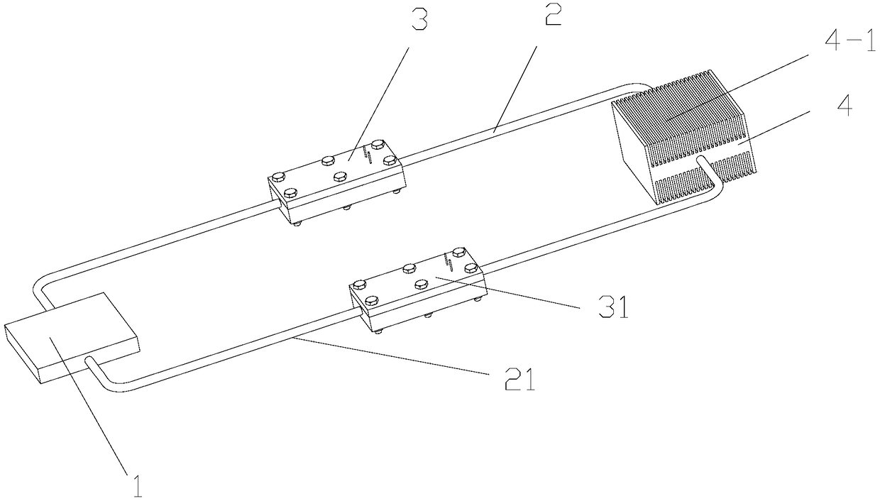
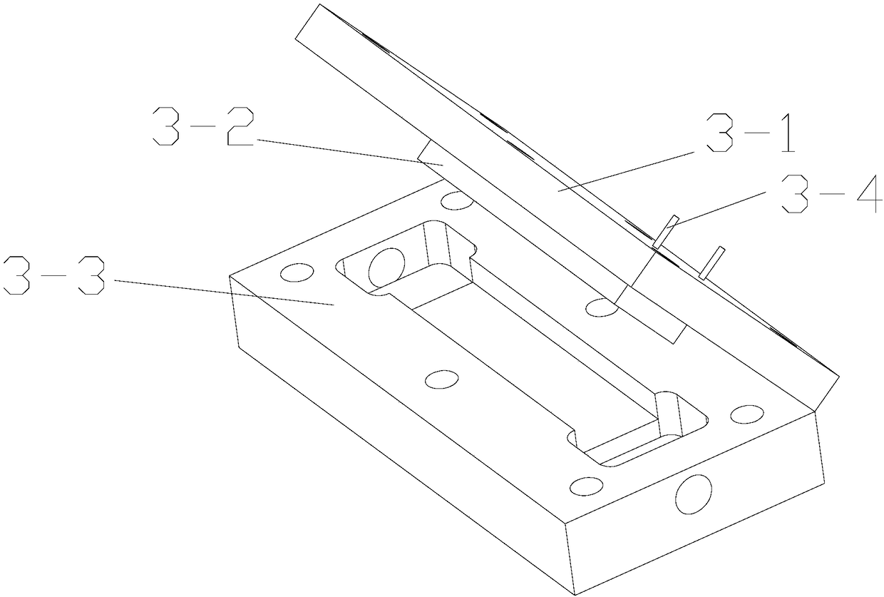
[0029] Such as Figures 1 to 3 shown. The invention discloses a small-sized liquid cooling system driven by an electro-hydraulic power micropump, comprising a liquid cooling block 1 filled with a liquid working medium and a heat exchanger 4 filled with a liquid working medium; the outlet of the heat exchanger 4 passes through The first loop pipeline 2 is connected to the inlet of the liquid cooling block 1, and the first electro-hydraulic power micropump 3 is connected in series on the pipeline of the first loop pipeline 2; the outlet of the liquid cooling block 1 passes through the second loop pipeline 21 The inlet of the heat exchanger 4 is connected, and a second electro-hydraulic power micropump 31 is connected in series on the pipeline of the second loop pipeline 21 .

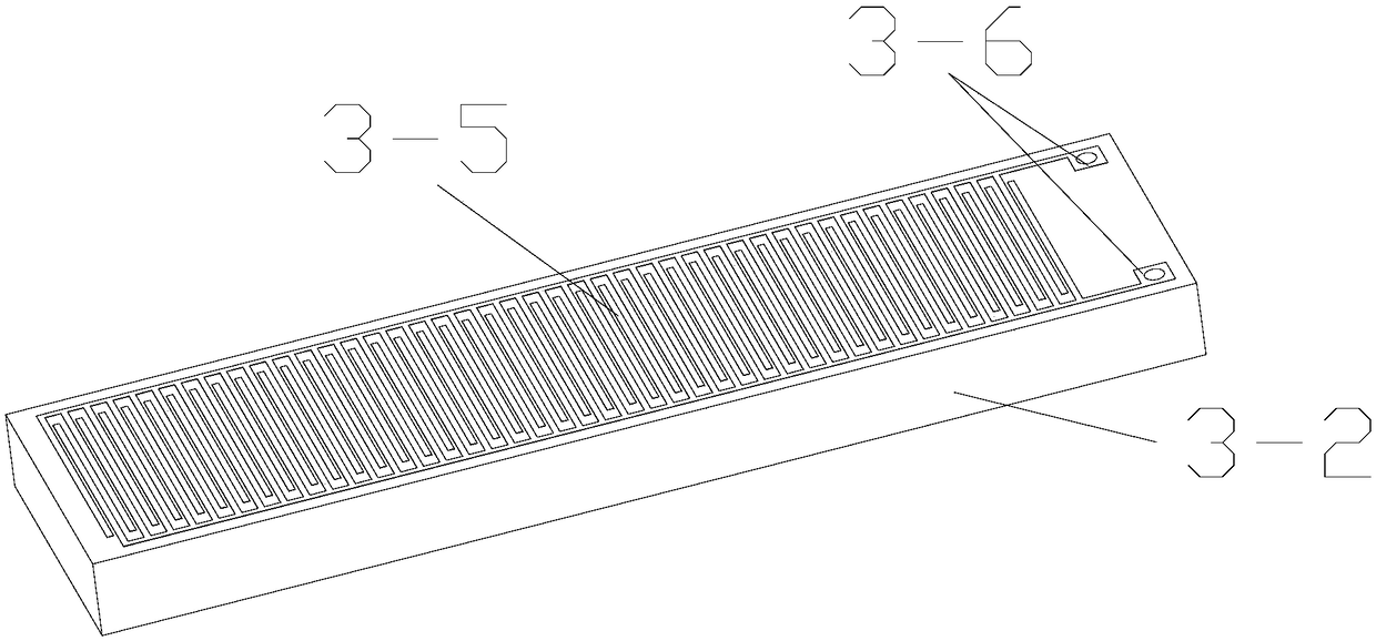
[0030] The first electro-hydraulic power micropump 3 includes a cavity 3-3, a sealing end cover 3-1 matched with the cavity 3-3, arranged on the inner surface of the sealing end cover 3-1 and extending to...


PUM


Abstract

The invention discloses a small liquid cooling system driven by electro-hydraulic micropumps and a method. The system comprises a liquid cooling block filled with liquid working fluid and a heat exchanger filled with liquid working fluid. An outlet of the heat exchanger is connected with an inlet of the liquid cooling block through a first loop pipeline. A first electro-hydraulic micropump is connected into a pipe of the first loop pipeline in series. An outlet of the liquid cooling block is connected with an inlet of the heat exchanger through a second loop pipeline. A second electro-hydraulic micropump is connected into a pipe of the second loop pipeline in series. The liquid cooling system not only solves the high-efficiency cooling problem of a large power electronic device, but also overcomes the defects of conventional mechanical pumps, such as large sizes, high power consumption, large noise, inaccurate flow control, etc. The system has advantages such as no moving parts, reliable operation, low power consumption, easy manufacturing and no need for maintenance. The system can be integrated with chips or channels directly and does not need independent space. The system can be applied to electronic cooling, drug transportation, micro-electro-mechanical system and other fields.

Description

technical field [0001] The invention relates to the field of fluid power and a heat transfer device, in particular to a small liquid cooling system and method driven by an electro-hydraulic power micropump. Background technique [0002] With the development of electronic manufacturing technology, the integration of electronic components is getting higher and higher. Moore's Law states that the transistor density of integrated circuits doubles every 18 months. The higher the integration of electronic components, the greater the heat flux. The reliability and life of electronic components will increasingly depend on the perfection of the thermal control system. Relevant studies have shown that for every 10°C increase in the operating temperature of electronic components, the reliability of the system and the life of electronic components will decrease by about half. At present, the heat dissipation power of high heat flow devices has reached the order of 10^6w / m^2, and the ...

Claims


Application Information

Patent Timeline
Patent Type & Authority Patents(China)
IPC IPC(8): H01L23/473
Inventor 万珍平冯晨莫海军陆龙生汤勇
Owner SOUTH CHINA UNIV OF TECH
Learn More