Power transmission case

A technology of power transmission box and box body, which is applied in the direction of transmission box, transmission device, transmission device parts, etc., can solve the problems that do not fully meet the needs of fast multi-functional work vehicles, mature products of power transmission box that do not meet working conditions, etc., and achieve structural Simple and practical, simple structure, large moment bearing capacity

Active Publication Date: 2014-03-26
CHANGZHOU RUITAI ENG MASCH CO LTD +1
View PDF6 Cites 2 Cited by
  • Summary
  • Abstract
  • Description
  • Claims
  • Application Information

AI Technical Summary

Problems solved by technology

[0007] There are mainly two foreign companies, STIEBEL and OMSI, which produce power transmission boxes, which are mainly used in construction vehicles, municipal sanitation vehicles, fire-fighting vehicles, etc., and there is no product in their p

Method used


Image

  • Power transmission case
  • Power transmission case
  • Power transmission case

Examples


Embodiment Construction

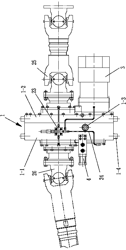
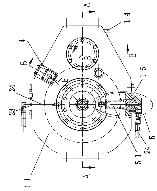
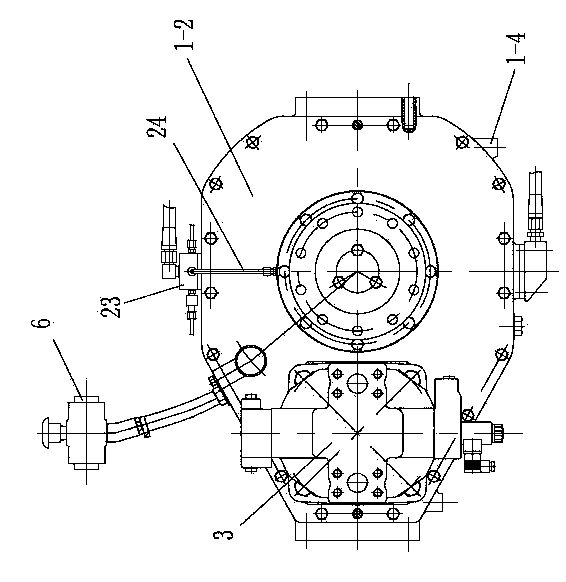
[0031] Such as figure 1 , 2 , 3, 4, and 5, a power transmission box of the present invention includes a box body 1, an input shaft 16, an output shaft 18, a driving gear 13, a driven gear 7, a shift clutch, a toggle mechanism 4, and a hydraulic The motor 3, the toggle mechanism 4 is mounted on the box 1, the hydraulic motor 3 is connected to the input shaft 16, the box 1 includes a left box 1-1 and a right box 1-2, the left box 1 -1 and the right casing 1-2 split planes are vertical planes, the driving gear 13 is constantly meshed with the driven gear 7, and the wheel hole of the driving gear 13 is provided with a bearing seat 13-1 and an internal spline 13-2 , Two ball bearings 12 are installed in the bearing seat 13-1, the driving gear 13 is rotatably supported on the input shaft 16 through the two ball bearings 12, the input shaft 16 has an external spline 16-1, the shift clutch It is composed of a gear shift sleeve 14, a gear sleeve positioning mechanism 17 and a driving ge...


PUM


Abstract

The invention discloses a power transmission case comprising a case body, an input shaft, an output shaft, a driving gear, a driven gear, a shift clutch, a toggle mechanism and a hydraulic motor. The case body comprises left case body and a right case body, subdivision surfaces of the left case body and the right case body are vertical planes, a bearing seat and an internal spline are arranged in a gear hole of the driving gear, two ball bearings are mounted in the bearing seat, the input shaft is provided with an external spline, the shift clutch is composed of a shift meshing sleeve, a meshing sleeve positioning mechanism and the internal spline of the driving gear, the meshing sleeve positioning mechanism is mounted on the input shaft, the shift meshing sleeve is provided with an internal spline and an external spline, the internal spline of the shift meshing sleeve is meshed with and in axial sliding fit with the external spline of the input shaft, the external spline of the shift meshing sleeve can be meshed with or separated from the internal spline of the driving gear, and the toggle mechanism comprises a toggle cylinder, a fork pull rod and a fork. The power transmission case is simple and reasonable in structure and easy to manufacture, the requirements for high-speed running and low-constant speed operating, running and driving of a rapid multifunctional operating vehicle are met.

Description

Technical field [0001] The invention relates to a track maintenance machine, in particular to a power transmission box for changing working conditions of engineering vehicles. Background technique [0002] Track maintenance machinery-fast multifunctional integrated operating vehicle, is a professional equipment for the overhaul, maintenance and emergency repair of the catenary of electrified railways and high-speed passenger dedicated lines. It can also be used for railway engineering vehicles for the inspection and maintenance of lines, bridges and other facilities. [0003] With the rapid development of my country's high-speed railways during the "Eleventh Five-Year Plan" period, up to now, more than 10,000 kilometers have been opened. Especially since the Beijing-Shanghai high-speed rail was put into operation, catenary accidents have occurred frequently, and the catenary has been quickly repaired and rescued. Ensuring the punctual operation of passenger trains will be the top pr...

Claims


Application Information

Patent Timeline
IPC IPC(8): F16H47/00F16H57/02F16H57/023F16H57/027F16H63/30
CPCF16H47/02F16H57/02F16H57/023F16H57/027F16H59/044F16H61/30F16H63/3408
Inventor 胡高华陈丽丽
Owner CHANGZHOU RUITAI ENG MASCH CO LTD
Why Eureka
Try Eureka