Torque control system and method of electric actuator

An electric actuator and torque control technology, which is applied in the direction of engine components, valve details, valve operation/release devices, etc., can solve problems such as low operating efficiency, low system stability, and slow response speed, and achieve R&D and production Convenience, advancement of technical level, promotion of improvement and development effect

Active Publication Date: 2014-03-26
上海国鼎数码科技有限公司
View PDF7 Cites 7 Cited by
  • Summary
  • Abstract
  • Description
  • Claims
  • Application Information

AI Technical Summary

Problems solved by technology

Traditional electric actuators sense torque mechanically or through pressure sensors. In practical applications, this method will encounter problems such as cumbersome setting of torque parameters, low system stability, low operating efficiency, and slow response speed.
Therefore, it cannot meet the comprehensive requirements of the industry for the accuracy, maintenance convenience and stability of the torque protection device of the control system

Method used


Image

  • Torque control system and method of electric actuator
  • Torque control system and method of electric actuator
  • Torque control system and method of electric actuator

Examples


Embodiment 1

[0052] Embodiment 1: Torque is detected through changes in capacitance value and frequency.

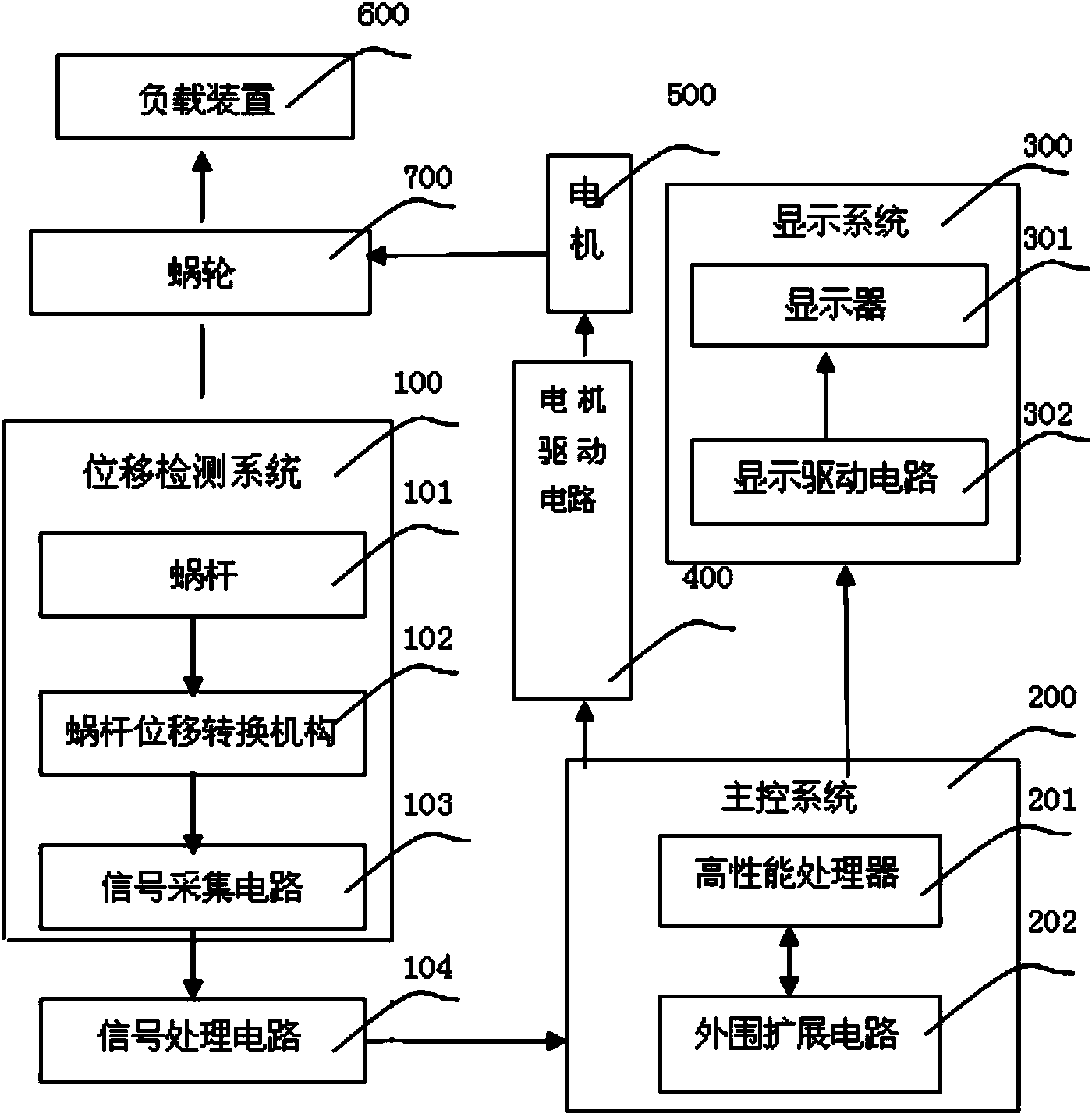
[0053]This example is based on the mechanical transmission mode of the worm, and adopts the non-invasive design to realize the intelligent device of torque dynamic real-time detection. When the worm of the mechanical transmission device undergoes axial displacement under force, the capacitive signal acquisition circuit collects the change of the mechanical displacement in real time to realize the calculation, calibration and protection of the torque.

[0054] The implementation process of the mechanical principle is described as follows:

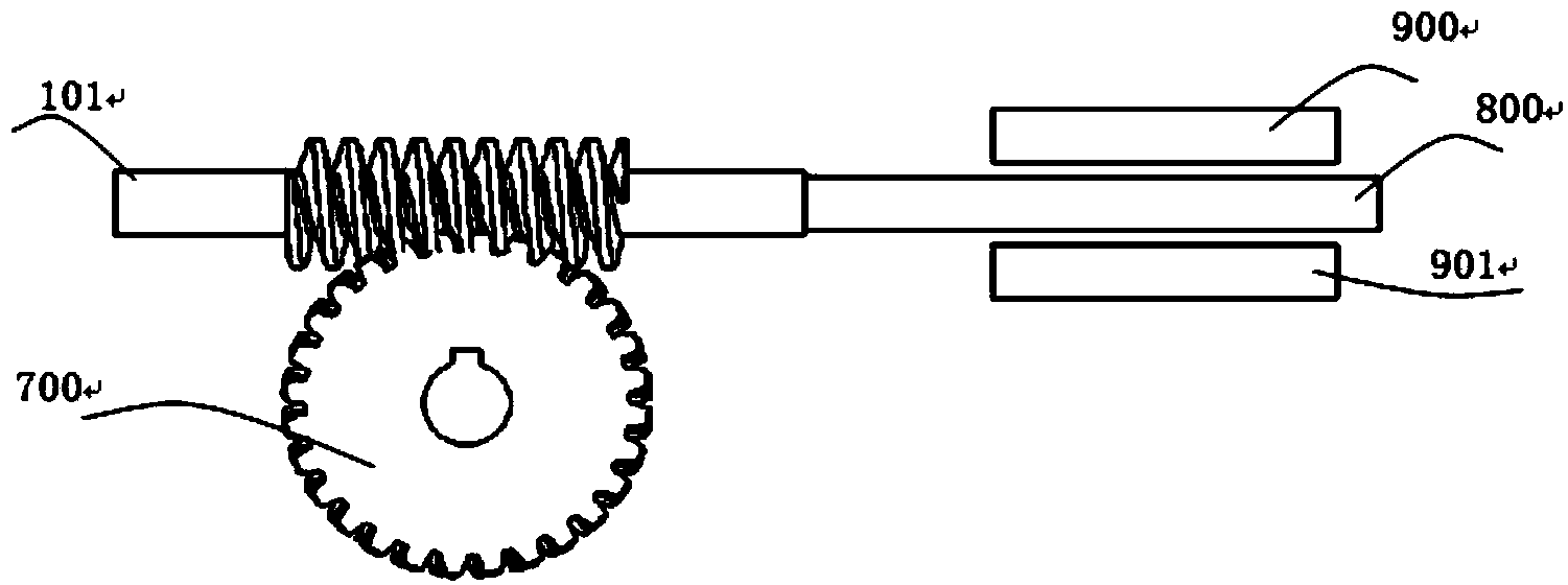
[0055] refer to image 3 , is a schematic diagram of the mechanical structure of capacitance value detection torque. The worm displacement conversion mechanism includes a ferrite core 800 arranged at the end of the worm 101 and a capacitor composed of a pair of parallel plates 900, 901. The ferrite core is placed in a pair of Between the parallel ...

Embodiment 2

[0066] Example 2: Detect displacement through changes in inductance and frequency

[0067] This example is based on the mechanical transmission mode of the worm, and adopts the non-invasive design to realize the intelligent device of torque dynamic real-time detection. When the worm gear of the mechanical transmission device undergoes axial displacement under force, the inductive signal acquisition circuit collects the change of the mechanical displacement in real time to realize the calculation, calibration and protection of the torque.

[0068] The implementation process of the mechanical principle is described as follows:

[0069] refer to Figure 5 , a schematic diagram of the mechanical structure of changing the inductance value to detect the torque, the worm displacement conversion mechanism includes a ferrite core 800 set at the end of the worm and an inductance winding 1000, the ferrite core 800 is placed in the hollow cylinder formed by the inductance winding 1000 T...

Embodiment 3

[0079] Embodiment 3: Detect displacement by angle sensor

[0080] This example is an intelligent device based on an angle sensor, which uses diagonal displacement acquisition and calculation to realize torque dynamic real-time detection. When the worm gear of the mechanical transmission device undergoes axial displacement under stress, the axial linear displacement is first converted into angular displacement through the corresponding mechanical structure, and then the angular displacement is detected by the sensor, so as to realize the calculation, calibration and protection of torque.

[0081] The implementation process of the mechanical principle is described as follows:

[0082] refer to Figure 7 , this example is based on the mechanical transmission mode of worm gear to realize the intelligent device of torque dynamic real-time detection;

[0083] Described worm displacement conversion mechanism comprises a screw mandrel 1001 that is provided with the end of worm screw...


PUM


Abstract

The invention discloses a torque control system and method of an electric actuator. The torque control system of the electric actuator comprises a main control system, a signal processing circuit connected with the main control system, and a displacement detecting system connected with the signal processing circuit, and further comprises a motor driving circuit, wherein the displacement detecting system comprise a signal collecting circuit; the signal collecting circuit transmits electric signal change parameters to the signal processing circuit after converting measurable physical displacement variation into the electric signal change parameters, and the signals are transmitted to the main control system after being amplified and shaped by the signal processing circuit; the motor driving circuit receives a control instruction of the main control system to adjust the rotation of a motor. By the utilization of the non-contact detection on the displacement, torque of the electric actuator is detected and controlled in real time. A convenience and efficient mode is provided for research, development and production of electric actuators and valve electric device control systems, and the technological level of the electric actuator industry is improved and developed.

Description

technical field [0001] The invention relates to an electric actuator torque control system and a control method thereof, which can realize real-time detection and protection of the electric actuator torque. Background technique [0002] At present, electric actuators and valve electric devices control valves and other field equipment to perform rotary or linear motion during the application field operation process, and the system dynamically adjusts the torque output of the system according to the demand of external loads. [0003] According to industry requirements, the system must be able to detect the torque output in real time during the actual working process of electric actuators and valve electric devices. Once the valve electric device is seized, the load is too large and other abnormal conditions occur, the torque output by the system will change; when When the main control system detects that the current torque value is greater than the torque protection threshold ...

Claims


Application Information

Patent Timeline
Patent Type & Authority Applications(China)
IPC IPC(8): F16K31/04F16K37/00
CPCF16K31/046F16K31/048F16K31/53F16K37/0075
Inventor 周虎英欧阳立坚王子威
Owner 上海国鼎数码科技有限公司
Why Eureka
Try Eureka